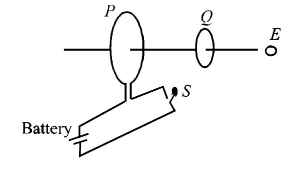
As shown in the figure, P and Q are two coaxial conducting loops separated by some distance. When the switch S is closed, a clockwise current `I_(P)` (as seen by E) and an induced current `I_(Q1)` flows in Q. The switch remains closed for a long time. when S is opened, a current `I_(Q2)` flows in Q. Then the direction `IQ_(1) and IQ_(2)` (as seen by E) are
A
respectively clockwise and anticlockwise
B
both clockwise
C
both anticlockwise
D
respectively anticlockwise and clockwise
Text Solution
Verified by Experts
The correct Answer is:
D
Topper's Solved these Questions
IIT QUESTIONS 3
D MUKHERJEE|Exercise Assertion -Reason type|2 Videos
IIT QUESTIONS 3
D MUKHERJEE|Exercise Linked -comprehension type|3 Videos
IIT QUESTIONS 2
D MUKHERJEE|Exercise Matrix matching type|1 Videos
IIT QUESTIONS 4
D MUKHERJEE|Exercise Integer type|10 Videos
Similar Questions
Explore conceptually related problems
In fig. A2.27, the charge that flows from P to Q when the switch S is closed is
In the circuit shown, the switch is closed at t=0 , the currents I_1, I_2 and I_3 are
When the switch S, in the circuit shown, is closed, then the value of current I will be :
The potential at points A and B are maintained at 20 V and 5 V as shown. When the switch S is closed, the current that flows through it is __________ A.
In the circuit shown in figure switch S is closed at time t=0 Current I from the battery at time t is given by
In the cricuit shown belew, the current that flows from a to b when switch S is closed is
Consider the circuit shown in figure. Find the current through the 10Omega resistor when the switch S is (a) opened (b) closed.
In the circuit shown switch S is closed at t=0 . Let i_1 and i_2 be the current at any finite time t then the ratio i_1/i_2
When the switch S, in the circuit shown , is closed , then the Value of current i will be :