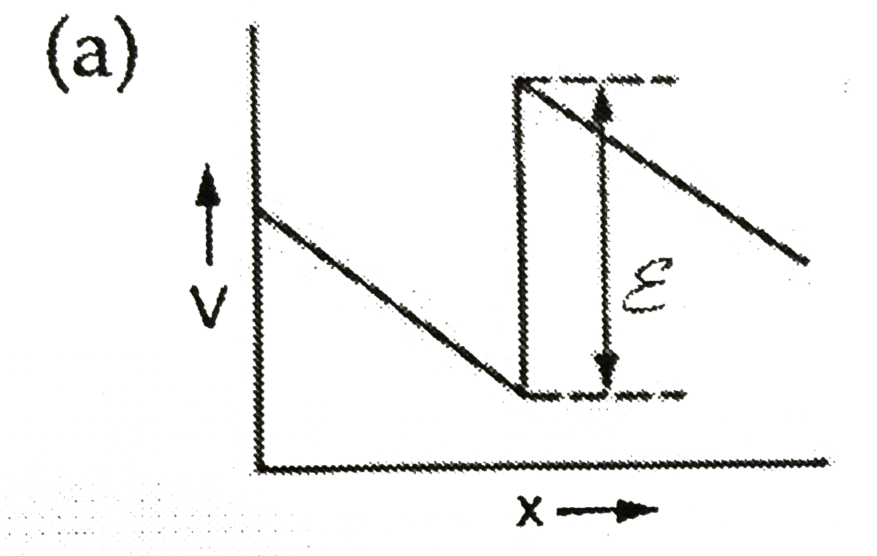
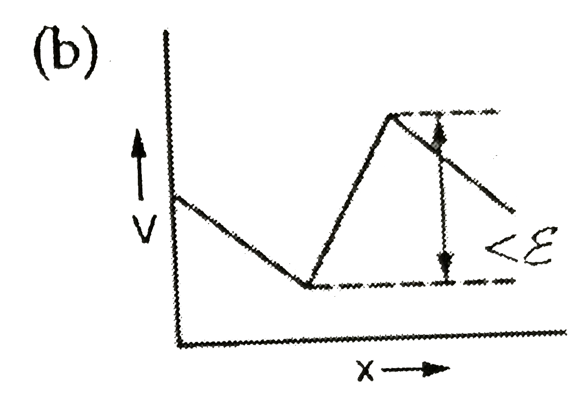
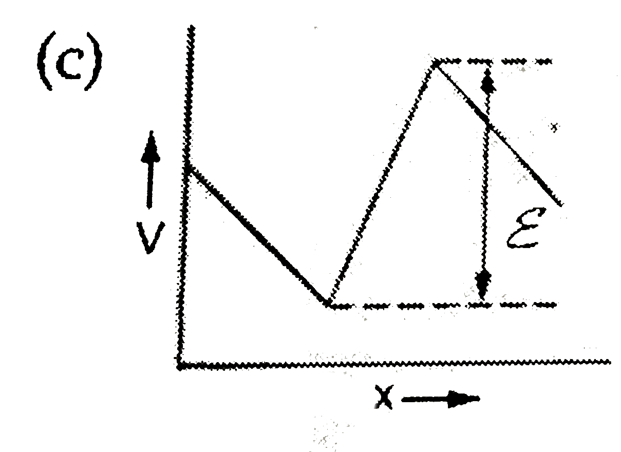
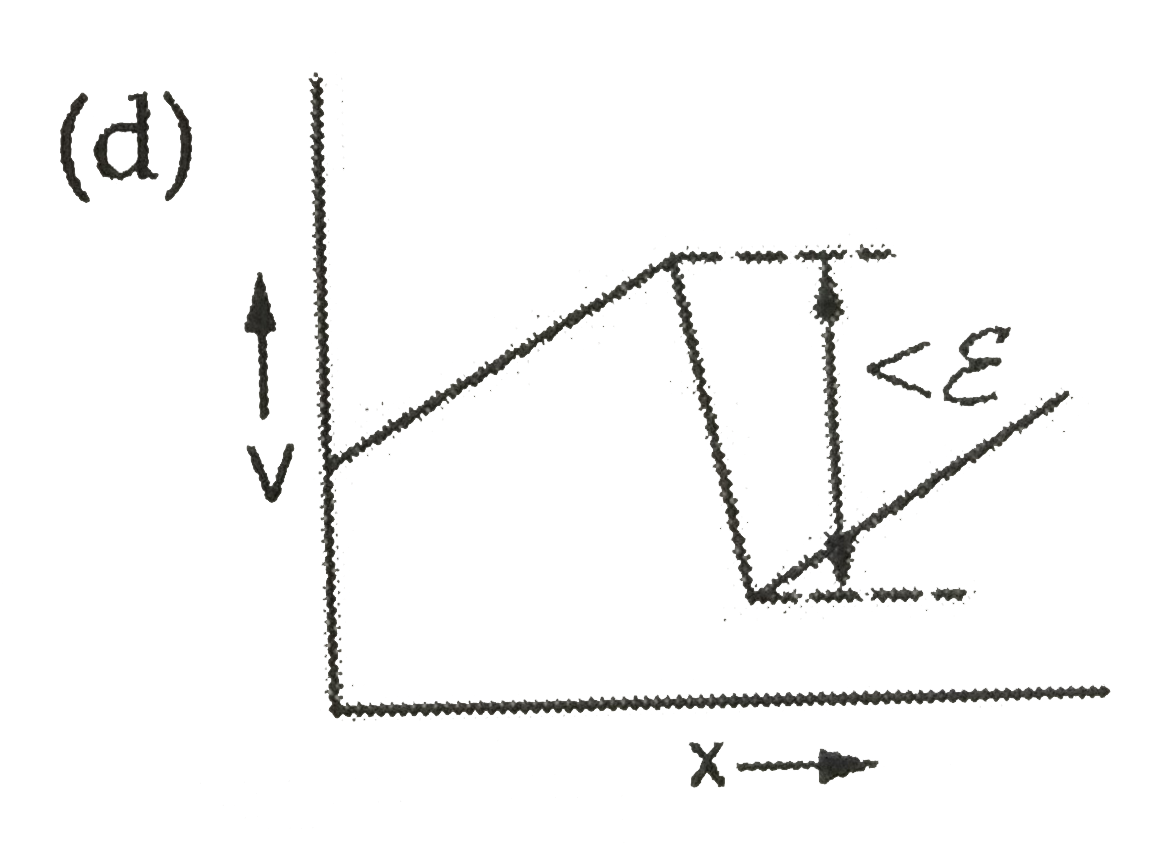
Home
Class 12
PHYSICS
The two ends of a uniform conductor are ...

The two ends of a uniform conductor are joined to a cell of e.m.f. `E` and some internal resistance. Starting from the midpoint `P` of the conductor, we move in the direction of current and return to `P`. The potential `V` at every point on the path is plotted against the distance covered `(x)`. which of the following graphs best represent the resulting curve ?

A

B

C

D

Text Solution

Verified by Experts

The correct Answer is:
B
Promotional Banner

Topper's Solved these Questions

  • CIRCULAR,ROTATIONAL & SIMPLE HARMONIC MOTION

    D MUKHERJEE|Exercise All Questions|88 Videos
  • ELECTROMAGNETISM

    D MUKHERJEE|Exercise All Questions|91 Videos

Similar Questions

Explore conceptually related problems

A thin, straight conductor lies along the axis of a hollow conductor of radius R . The two carry equal currents in the same direction. The magnetic field B is plotted against the distance r from the axis. Which of the following best represents the resulting curve?

A square, conducting loop falls from rest in the xy-plane. There is a uniform magnetic field in the z-direction below the x-axis. The velocity v of the loop is plotted against time t. Which of the following best represents the resulting curve

A current of two amperes is flowing through a cell of e.m.f. 5 volts and internal resistance 0.5 ohm from negative to positive electrode. If the potential of negative electrode is 10 V , the potential of positive electrode will be

Two ideantical point charges are placed at a separation of d . P is a point on the line joining the charges, at a distance x from any one charge. The field at P is E, E is plotted against x for value of x from close to zero to slightly less then d . Which of the following represents the resulting curve

E denotes electric field in a uniform conductor, I corresponding current through it, v_(d) velocity of electrons and P denotes thermal power produced in the conductor, then which of the following graph is correct?

A battery of e.m.f. 2 V and internal resistance 2Omega is connected to an external resistance 8Omega . If the length of the conductor is 4 m, then potential gradient between the two ends of the wire is

Two batteries of e.m.f. 4V and 8V with internal resistances 1 Omega and 2 Omega are connected in a circuit with a resistance of 9 Omega as shown in figure. The current and potential difference between the points P and Q

D MUKHERJEE-ELECTRIC CURRENT IN CONDUCTORS-All Questions
  1. In the network shown, each resistance is equal to R. The equivalent re...

    Text Solution

    |

  2. In the network shown in figure, the ring has zero resistance. Find the...

    Text Solution

    |

  3. The two ends of a uniform conductor are joined to a cell of e.m.f. E a...

    Text Solution

    |

  4. The emf of a cell is epsilon and its internal resistance is r. its ter...

    Text Solution

    |

  5. N identical cells are connected to form a battery. When the terminals ...

    Text Solution

    |

  6. N identical cells, each emf E and internal resistance r are joined in ...

    Text Solution

    |

  7. n identical cells, each of emf E and internal resistance r, are joined...

    Text Solution

    |

  8. n identical cells, each of emf epsilon and internal resistance r, are ...

    Text Solution

    |

  9. In the circuit shown above, the conductor XY is of negligible resisanc...

    Text Solution

    |

  10. The Wheatstone bridge shown in the above figure is balanced. If the po...

    Text Solution

    |

  11. In the circuti shown above the the voltmeter is of large resistance. T...

    Text Solution

    |

  12. A Galvanometer of range 10 mA has a coli of resistance 1 Omega. To use...

    Text Solution

    |

  13. A milliammeter of range of 10 mA gives full-scale deflection for a cur...

    Text Solution

    |

  14. A, B and C are voltmeters of resistances R, 1.5R and 3R respectively. ...

    Text Solution

    |

  15. An ammeter and a voltmeter are joined in sereis to a cell. Their readi...

    Text Solution

    |

  16. Acell of internal resistance r drives a current through an external re...

    Text Solution

    |

  17. When an electric heater is switched on, the current flowing through it...

    Text Solution

    |

  18. Figure 7.37 shows a network of three resistances. When some potential...

    Text Solution

    |

  19. An electric bulb is designed to draw P(0) power at V(0) voltage. If t...

    Text Solution

    |

  20. An electric bulb rated for 500 watts at 100 volts is used in a circuit...

    Text Solution

    |