


Topper's Solved these Questions
ELECTROMAGNETIC INDUCTION AND ALTERNATING CURRENT
PHYSICS GALAXY - ASHISH ARORA|Exercise Illustration|25 VideosELECTROMAGNETIC INDUCTION AND ALTERNATING CURRENT
PHYSICS GALAXY - ASHISH ARORA|Exercise Practice Exercise 5.1|12 VideosCURRENT ELECTRICITY
PHYSICS GALAXY - ASHISH ARORA|Exercise All Questions|389 VideosELECTROSTATICS
PHYSICS GALAXY - ASHISH ARORA|Exercise Unsolved Numberical Problems|73 Videos
Similar Questions
Explore conceptually related problems
PHYSICS GALAXY - ASHISH ARORA-ELECTROMAGNETIC INDUCTION AND ALTERNATING CURRENT-Advance MCQs
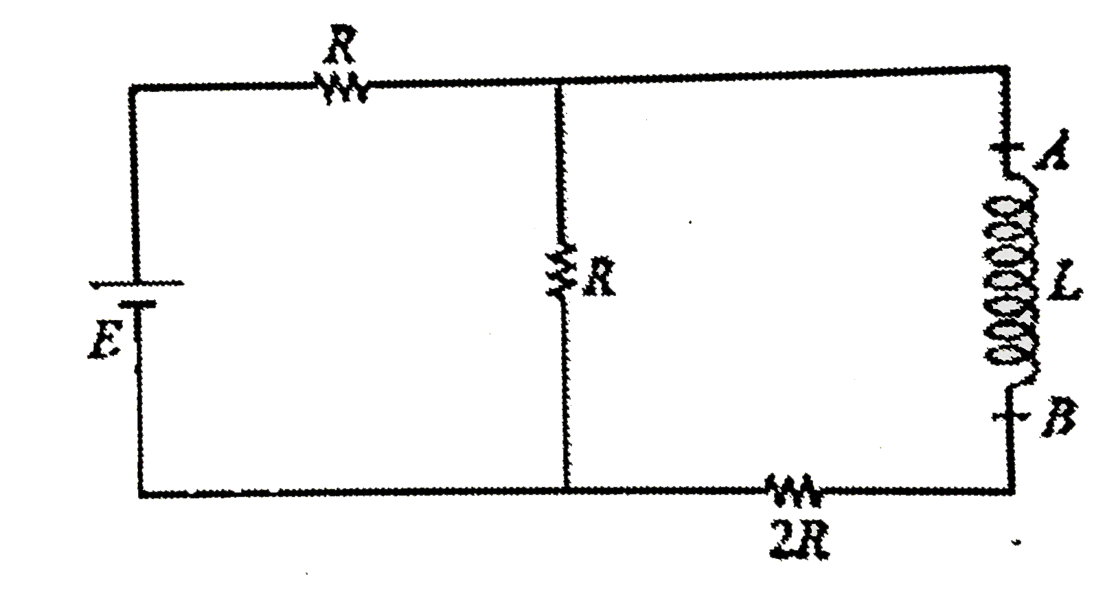
- Figure-5.102 shows a RL circuit. If at t-0 switch is closed, find the ...
Text Solution
|
- A loop is kept so that its center lies at the origin of the coordinate...
Text Solution
|
- For a RLC series circuit , phasors of current i and applied voltage V=...
Text Solution
|
- Two different coils have self-inductances L(1) = 8 mH and L(2) = 2 mH....
Text Solution
|
- Mutual inductance of two coils can be increased by
Text Solution
|
- Which of the following statements is/are correct?
Text Solution
|
- The loop shown moves with a velocity v in a uniform magnetic field of ...
Text Solution
|
- In the following electrical network at t lt 0, key is placed on (1) ti...
Text Solution
|
- An infinitely longg wire is placed near a square loop as shown in figu...
Text Solution
|
- A circuit is set up by connecting L=100mH, C=5muF and R=100Omega in se...
Text Solution
|
- Choose the CORRECT statements:
Text Solution
|
- For an LCR series circuit with an aac source of angular frequency omeg...
Text Solution
|
- In the circuit shown in figure, circuit is closed at time t=0. At time...
Text Solution
|
- Choose the CORRECT statement(s) in the following:
Text Solution
|
- In the circuit shown in figure-5.318, if both the bulbs B(1) and B(2) ...
Text Solution
|
- Two circular coils are placed adjacent to each other. Their planes are...
Text Solution
|
- AB and CD are fixed conducting smooth rails placed in a vertical plane...
Text Solution
|
- A coil of area 2m^2 and resistane 4Omega is placed perpendicular to a ...
Text Solution
|
- A circuit consisting of a constant EMF E, a self-inductance L and a re...
Text Solution
|
- In LC oscillations of a capacitor with an initial charge q(0) is conne...
Text Solution
|
- A solenoid is connedted to a source of constant EMF for a long time. A...
Text Solution
|