A
B
C
D
Text Solution
Verified by Experts
The correct Answer is:


Topper's Solved these Questions
ELECTROMAGNETIC INDUCTION AND ALTERNATING CURRENT
PHYSICS GALAXY - ASHISH ARORA|Exercise Advance MCQs|33 VideosELECTROMAGNETIC INDUCTION AND ALTERNATING CURRENT
PHYSICS GALAXY - ASHISH ARORA|Exercise Conceptual MCQs|63 VideosCURRENT ELECTRICITY
PHYSICS GALAXY - ASHISH ARORA|Exercise All Questions|389 VideosELECTROSTATICS
PHYSICS GALAXY - ASHISH ARORA|Exercise Unsolved Numberical Problems|73 Videos
Similar Questions
Explore conceptually related problems
PHYSICS GALAXY - ASHISH ARORA-ELECTROMAGNETIC INDUCTION AND ALTERNATING CURRENT-Numerical MCQs
- In a step up transformer, the turn ratio is 3 : 2. A battery of EMF 4....
Text Solution
|
- A flat circular coil of n turns, area A and resitance R is placed in a...
Text Solution
|
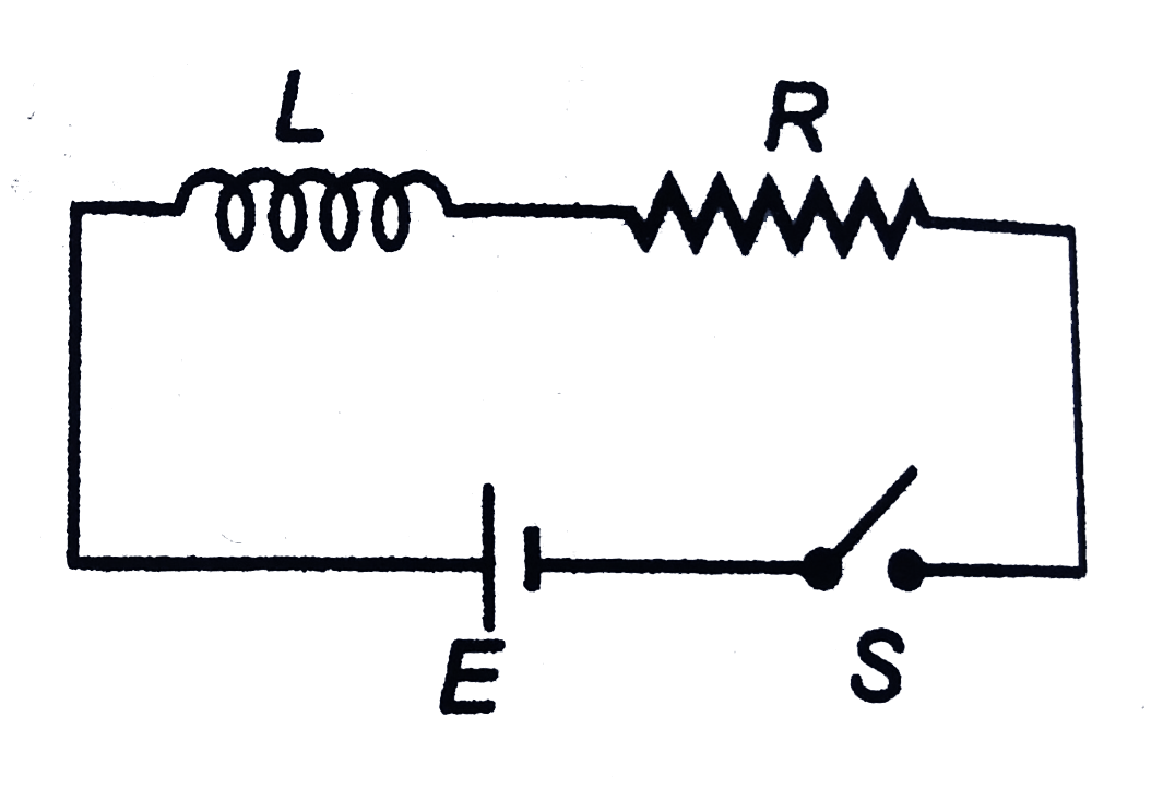
- In the circuit shown in figure L=10H, R=5Omega, E=15V. The switch S is...
Text Solution
|
- In an AC circuit, V and I are given by V=100sin(100t)volts, I=100sin(1...
Text Solution
|
- The ratio of secondary to the primary turns in a transformer is 3:2. I...
Text Solution
|
- Two ends of an inductor of inductance L are connected to two parallel ...
Text Solution
|
- A 40Omega electric heater is connected to a 200V, 50Hz main supply. Th...
Text Solution
|
- A transformer is used to light a 100 W and 110 V lamp from a 220V main...
Text Solution
|
- Two parallel long straight conductors lie on a smooth plane surface. T...
Text Solution
|
- An alternating voltage is connected in series with a resistance R and ...
Text Solution
|
- A magnet is taken towards a conducting ring in such a way that a const...
Text Solution
|
- A conducnting straight wire PQ of length l is fixed along as diameter ...
Text Solution
|
- An inductive circuit a resistance of 10ohm and an inductance of 2.0 h...
Text Solution
|
- A rectangular loop with a sliding connector of length 10 cm is situate...
Text Solution
|
- A 20volts AC is applied to a circuit consisting of a resistance and a...
Text Solution
|
- A square loop of side b is rotated in a constant magnetic field B at a...
Text Solution
|
- A resistance of 300Omega and an inductance of 1/(pi) henry are connect...
Text Solution
|
- An inductor L and a capacitor C are connected in the circuit as shown ...
Text Solution
|
- Switch S is closed t=0, in the circuit shown. The change in flux in th...
Text Solution
|
- An electric current i(1) can flow in either direction through loop-1 a...
Text Solution
|