A
B
C
D
Text Solution
Verified by Experts
The correct Answer is:


Topper's Solved these Questions
Similar Questions
Explore conceptually related problems
DC PANDEY-ELECTROSTATICS-Comprehension
- In the figure m(A) = m(B) = 1 kg. Block A is neutral while q(B) = -1C....
Text Solution
|
- In the figure m(A) = m(B) = 1 kg. Block A is neutral while q(B) = -1C....
Text Solution
|
- In the figure m(A) = m(B) = 1 kg. Block A is neutral while q(B) = -1C....
Text Solution
|
- A solid conducting sphere of radius 'a' is surrounded by a thin unchar...
Text Solution
|
- A solid conducting sphere of radius 'a' is surrounded by a thin unchar...
Text Solution
|
- A solid conducting sphere of radius 'a' is surrounded by a thin unchar...
Text Solution
|
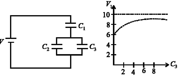
- Capacitor C(3) in the circuit is a veriable capacitor (its capacitance...
Text Solution
|
- Capacitor C(3) in the circuit is a veriable capacitor (its capacitance...
Text Solution
|
- Capacitor C(3) in the circuit is variable capacitor (its capacitance c...
Text Solution
|
- Four metallic plates placed as shown in the figure. Plate 2 is given a...
Text Solution
|
- Four metallic plates placed as shown in the figure. Plate 2 is given a...
Text Solution
|
- Four large identical metallic plates are placed as shown in the Figure...
Text Solution
|
- The figure shows a arrangement of capacitors and a battery. Iden...
Text Solution
|
- The figure shows a arrangement of capacitors and a battery. If t...
Text Solution
|
- The figure shows a arrangement of capacitors and a battery. The ...
Text Solution
|
- In the circuit shown in the figure, in steady state: The charge o...
Text Solution
|
- In the circuit shown in the figure, in steady state: The current ...
Text Solution
|
- Four large metallic plates of area A each are kept parallel to each ot...
Text Solution
|
- Four large metallic plates of area A each are kept parallel to each ot...
Text Solution
|
- Four large metallic plates of area A each are kept parallel to each ot...
Text Solution
|