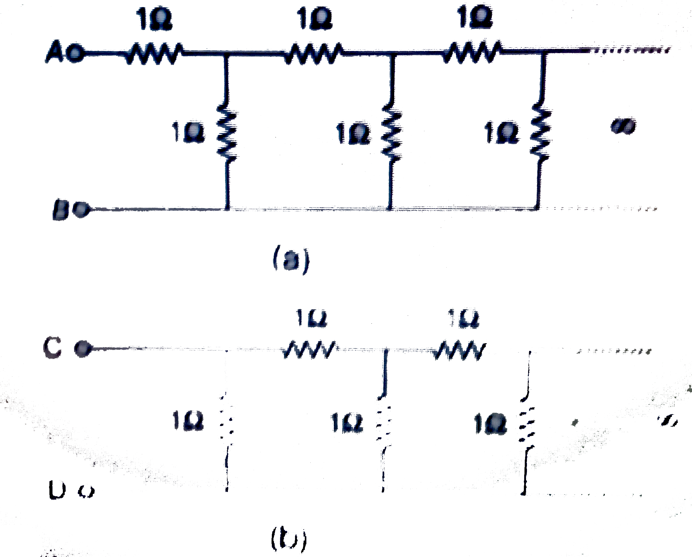
A
B
C
D
Text Solution
Verified by Experts
The correct Answer is:
Topper's Solved these Questions
Similar Questions
Explore conceptually related problems
DC PANDEY-CURRENT ELECTRICITY-All Questions
- Find equivalent resistance between A and B
Text Solution
|
- Two identical batteries, each having emf of 1.8 V and of equal interna...
Text Solution
|
- In the two circuits shown in figure
Text Solution
|
- The net resistance between points P and Q in the circuit shown in figu...
Text Solution
|
- Current in 3 Omega resistance is
Text Solution
|
- A galvanometer of resistance R(G) is to be converted into an ammeter, ...
Text Solution
|
- The equivalent resistance between points A and B
Text Solution
|
- In the circuit shown in figure, each resistance is Net resistance betw...
Text Solution
|
- In the same figure, equivalent resistance between points A and D is
Text Solution
|
- Each resistance of the circuit shown in figure is r. The equivalent re...
Text Solution
|
- As shown, the circuit is made of 8 different resistance. It is found t...
Text Solution
|
- Resistance of each resistor is R. Then the equivalent resistance acros...
Text Solution
|
- In the given circuit the power dissipated through resistance R(1) = 9 ...
Text Solution
|
- A copper disc and a carbon disc of same radius are assembled alternate...
Text Solution
|
- Find equivalent resistance between A and B
Text Solution
|
- Find equivalent resistance between A and D
Text Solution
|
- Calculate equivalent resistance between A and C
Text Solution
|
- In the circuit shown below, V should be:
Text Solution
|
- Equivalent resistance between A and B is
Text Solution
|
- In the circuit shown in figure, power developed across 1 Omega, 2 Omeg...
Text Solution
|
