A
B
C
D
Text Solution
Verified by Experts
The correct Answer is:


Topper's Solved these Questions
Similar Questions
Explore conceptually related problems
DC PANDEY-CURRENT ELECTRICITY-All Questions
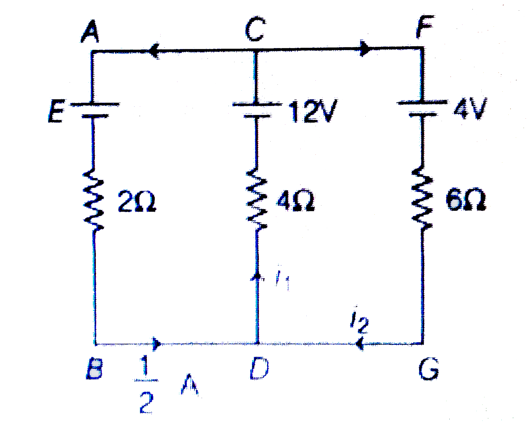
- In the circuit shown in figure
Text Solution
|
- A microameter has a resistance of 100 omega and a full scale range of ...
Text Solution
|
- In the circuit shown in figure
Text Solution
|
- A voltmeter reads the potential difference across the terminals of an ...
Text Solution
|
- A battery of emf E and internal resistance r is connected across a res...
Text Solution
|
- In the circuit shown in figure
Text Solution
|
- Two bulbs consume same energy when operated at 200 V and 300 V , respe...
Text Solution
|
- Potential difference across the terminal of a non ideal battery is
Text Solution
|
- The resistance of an ideal ammeter is
Text Solution
|
- In the circuit shown in figure resistance of each wire is r. Net resis...
Text Solution
|
- In the circuit shown in figure, power generated in
Text Solution
|
- In the circuit shown in figure
Text Solution
|
- Figure shows part of a circuit. Which points have the same potential a...
Text Solution
|
- In a potentiometer wire experiment the emf of a battery in the primary...
Text Solution
|
- In the network shown in fig. , points A, B, and C are at potentials of...
Text Solution
|
- The value of the resistance R in figure is adjusted such that power di...
Text Solution
|
- In the circuit shown E, F, G and H are cells of emf 2V, 1V, 3V and 1V ...
Text Solution
|
- A 20 m long potentiometer wire has a resistance of 20 Ohm. It is conne...
Text Solution
|
- In the circuit shown, both cells are ideal and of fixed emf, the resis...
Text Solution
|
- Two identical voltmeters and two identical ammeter are connected to a ...
Text Solution
|