A
B
C
D
Text Solution
Verified by Experts
The correct Answer is:


Topper's Solved these Questions
Similar Questions
Explore conceptually related problems
DC PANDEY-CURRENT ELECTRICITY-All Questions
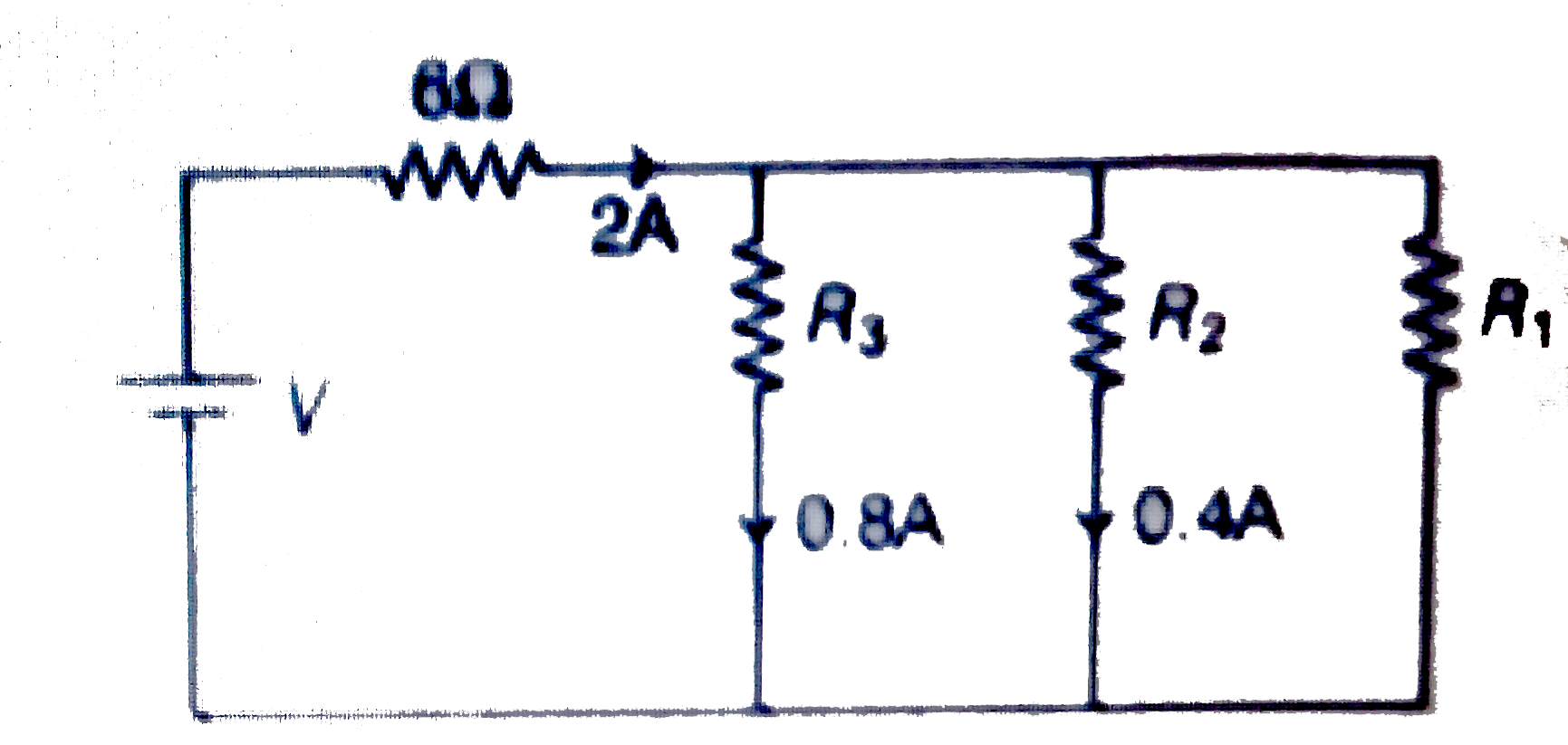
- In the circuit shown in figure
Text Solution
|
- The current density in a wire is 10A//cm^(2) and the electric field in...
Text Solution
|
- A resistor of resistance R is connected to a cell internal resistance ...
Text Solution
|
- Find the current through the 10(Omega)resistor shown in figure.
Text Solution
|
- Each resistance shown in the network is in ohm. Current through the re...
Text Solution
|
- The forward biased conection is :
Text Solution
|
- Four identical bulbs each rated 100 watt, 220 volts are connected acro...
Text Solution
|
- The reading of voltmeter is
Text Solution
|
- The ammeter shown in figure consists of a 480 Omega coil connected in ...
Text Solution
|
- When a galvanometer is shunted with a 4 Omega resistance, the deflecti...
Text Solution
|
- In the figure shown the current flowing 2 R is:
Text Solution
|
- The equivalent resistance between the points A and B is:
Text Solution
|
- In the circuit shown, what is the potential different V(PQ) ?
Text Solution
|
- Which of the following wiring diagrams could be used to experimentally...
Text Solution
|
- In the given circuit current flowing through the resistance 20Omega is...
Text Solution
|
- Power generated across a uniform wire connected across a supply is H. ...
Text Solution
|
- Rate of dissipation of Joule's heat in resistance per unit volume is (...
Text Solution
|
- The variation of current (I) and voltage (V) is as shown in figure A. ...
Text Solution
|
- Six resistors each of 10 ohm are connected shown. The equivalent resis...
Text Solution
|
- Thirteen resistances each of resistance R ohm are connected in the cir...
Text Solution
|
- In the given network, the euqivalent resistance between A and B is
Text Solution
|