Home
Class 11
PHYSICS
Two identical voltmeters and two identic...

Two identical voltmeters and two identical ammeter are connected to a battery of negligible resistance shown in the figure. The readings of devices are follows

Reading of Ammeter `A_(1) = 200 muA`
Reading of voltmeter `V_(2) = 2` volt
Reading of voltmeter `V_(1) = 100` volt
Choose the correct option(s)

A

Reading of ammeter `A_(2)` is `196 muA`

B

Resistance of voltmeter is `0.5 M Omega`

C

Resistance of ammeter is `10.2 kOmega`

D

Current passing through voltmeter `V_(2)` is `4 muA`

Text Solution

Verified by Experts

The correct Answer is:
A, B, C, D
Promotional Banner

Topper's Solved these Questions

  • COMMUNICATION SYSTEM

    DC PANDEY|Exercise Only One Option is Correct|27 Videos
  • ELASTICITY

    DC PANDEY|Exercise Medical entrances s gallery|21 Videos

Similar Questions

Explore conceptually related problems

If reading of voltmeter V_(1) is 40 V, what is the reading of voltmeter V_(2) ?

A circuit is shown in the figure. The ratio of readings of ideal voltmeter to reading of ideal ammeter is

[" A non-ideal voltmeter and a non-ideal ammeter are connected as shown in the figure.The reading of "],[" the voltmeter is "20V" and that of the ammeter is "4A" .The value of "R" is : "]

If by mistake Ammeter is connected parallel to the resistance then i-V curve expected is (Here i = reading of ammeter, V= reading of voltmeter)

[" A non-ideal voltmeter and a non-ideal ammeter are connected as shown in the figure.The reading of "],[" the voltmeter is "20V" and that of the ammeter is "4A" .The value of "R" is : "],[qquad (A)/(0)]

In the circuit shown in figure reading of voltmeter is V_(1) when only S_(1) is closed , reading of voltmeter is V_(2) when only S_(2) is closed . The reading of voltmeter is V_(3) when both S_(1) and S_(2) are closed then

An ammeter A, a voltmeter V and a resistance R are connected as shown in the figure. If the voltmeter reading is 1.6V and the ammeter reading is 0.4 A, then R is

DC PANDEY-CURRENT ELECTRICITY-All Questions
  1. A 20 m long potentiometer wire has a resistance of 20 Ohm. It is conne...

    Text Solution

    |

  2. In the circuit shown, both cells are ideal and of fixed emf, the resis...

    Text Solution

    |

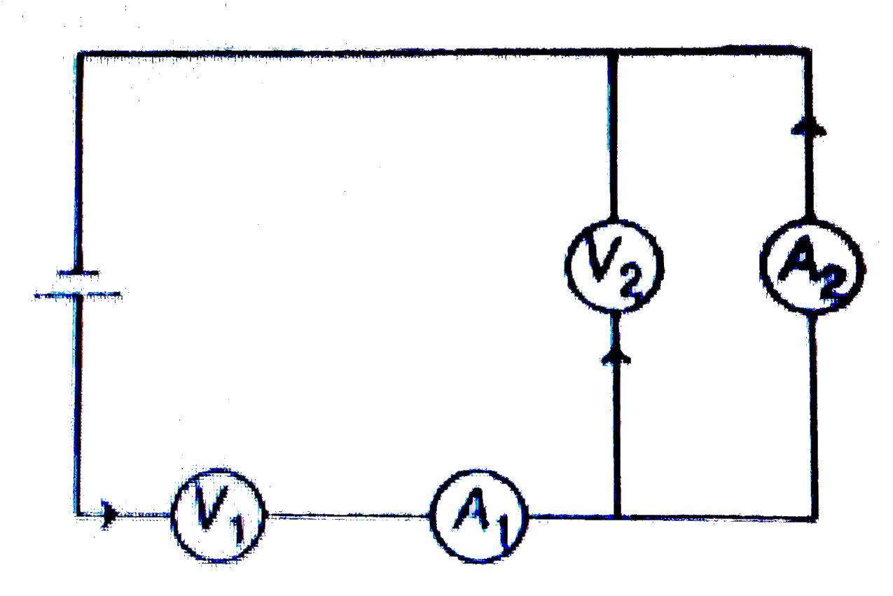
  3. Two identical voltmeters and two identical ammeter are connected to a ...

    Text Solution

    |

  4. In the circuit shown, total power supplied by an ideal battery is 80 W...

    Text Solution

    |

  5. In the circuit shown, total power supplied by an ideal battery is 80 W...

    Text Solution

    |

  6. In the circuit shown, total power supplied by an ideal battery is 80 W...

    Text Solution

    |

  7. In the circuit shown in figure Current through R(2) is zero if R...

    Text Solution

    |

  8. In the circuit shown in figure Current thorugh R(1) is independen...

    Text Solution

    |

  9. In the circuit shown in figure For what ratio (R(2))/(R(4)), curr...

    Text Solution

    |

  10. For the circuit shown figure answer the following questions For w...

    Text Solution

    |

  11. For the circuit shown figure answer the following questions For t...

    Text Solution

    |

  12. In series, potential difference distributes in direct ratio of resista...

    Text Solution

    |

  13. In series, potential difference distributes in direct ratio of resista...

    Text Solution

    |

  14. In the circuit shown in figure points a, b and c are maintained at con...

    Text Solution

    |

  15. In the circuit shown in figure points a, b and c are maintained at con...

    Text Solution

    |

  16. All bulbs consume same power. The resistance of bulb 1 is 36 Omega . ...

    Text Solution

    |

  17. All bulbs consume same power. The resistance of bulb 1 is 36 Omega . ...

    Text Solution

    |

  18. All bulbs consume same power. The resistance of bulb 1 is 36 Omega . ...

    Text Solution

    |

  19. The power dissipated in resistor R(3) shown in the figure is 15 W. The...

    Text Solution

    |

  20. The power dissipated in resistor R(3) shown in the figure is 15 W. The...

    Text Solution

    |