Text Solution
Verified by Experts
The correct Answer is:


Topper's Solved these Questions
Similar Questions
Explore conceptually related problems
DC PANDEY-CURRENT ELECTRICITY-All Questions
- Six batteris of increasing emf and increasing internal resistance are ...
Text Solution
|
- In the potentiometer arrangement shown in figure null point is obtaine...
Text Solution
|
- In the circuit shown in figure, if a resistance R connected in parall...
Text Solution
|
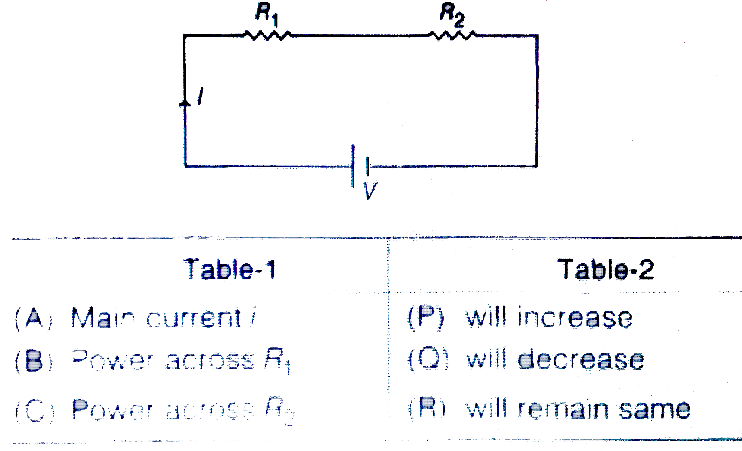
- In the circuit shown in figure, match following.
Text Solution
|
- Current is flowing through a wire of non-uniform cross section. Cross ...
Text Solution
|
- In the circuit shown in figure, match the match the following
Text Solution
|
- the following table gives the lengths of four copper rods at the tempe...
Text Solution
|
- the current in a circuit containing a battery connected to 2Omega resi...
Text Solution
|
- Equivalent resistance between points A and B is 0.5 xR. Find value of ...
Text Solution
|
- Three electric bulbs of 200 W and 400 W are shown in figure. The resu...
Text Solution
|
- In the circuit shown it figure ,a voltmeter of internal resistance R, ...
Text Solution
|
- An electric current of 16 A exists in a metal wire of cross section 10...
Text Solution
|
- Two wires A and B made of same material and having their lengths in th...
Text Solution
|
- In the given circuit diagram find the potential difference across 2 Om...
Text Solution
|
- In the circuit shown in figure ,find the ratio of currents i(1)//i(2).
Text Solution
|
- Find the current ( in ampere) through wire XY of the circuit shown in ...
Text Solution
|
- the current in resistance R(3) in the given circuit is 2/x A. Find the...
Text Solution
|
- In the circuit as shown in figure , the reading of ammeter (ideal) in ...
Text Solution
|
- For the potentiometer arrangement shown in the figure, length of wire ...
Text Solution
|
- For the arrangement of the potentimeter shown in the figure, The balan...
Text Solution
|