


Topper's Solved these Questions
ELECTRICAL INSTRUMENTS
SL ARORA|Exercise Problem for self practice|81 VideosELECTRICAL INSTRUMENTS
SL ARORA|Exercise Problem for self practice|81 VideosELECTRIC POTENTIAL AND ELECTRIC FLUX
SL ARORA|Exercise Problems for self practive|61 VideosELECTROMAGNETIC INDUCTION
SL ARORA|Exercise All Questions|108 Videos
Similar Questions
Explore conceptually related problems
SL ARORA-ELECTRICAL INSTRUMENTS-Problem From competitive examinations
- In the circuit shown in figure. The cells E,F,G and H have e.m.f's 2,1...
Text Solution
|
- In the circuit in figure E1=3V, E2=2V, E3=1V and R=r1-r2-r3=1Omega ...
Text Solution
|
- A part of the circuit in a steady state along with the currents flowin...
Text Solution
|
- In the circuit shown in figure. epsi(1)=3,epsi(2)=2,epsi(3)=6V,R(1)=2,...
Text Solution
|
- Find currents I(1),I(2) and I(3) and the energy stored in the capacito...
Text Solution
|
- An electrical circuit is shown in figure. Calculate the potential diff...
Text Solution
|
- In the network as shown in figure. Each resistance r is of 2Omega find...
Text Solution
|
- A galvanometer having 30 divisions has a current sensitivity of 20 muA...
Text Solution
|
- A potentiometer wire of length 100 cm has a resistance of 100Omega it ...
Text Solution
|
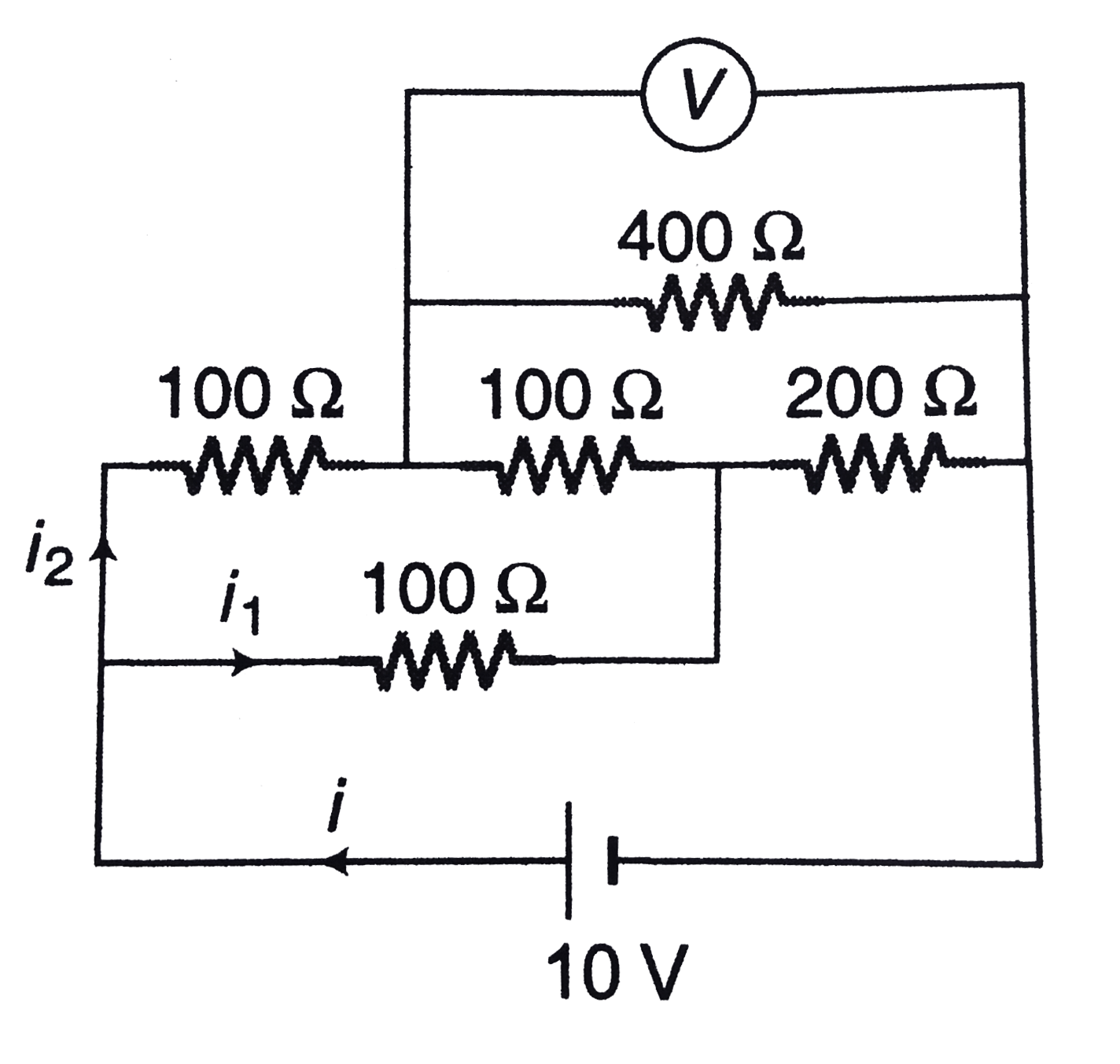
- In the arrangement of resistances shown in figure. Find the value of u...
Text Solution
|
- In figure. ABCD is a square where side is a uniform wire of resistance...
Text Solution
|