A
B
C
D
Text Solution
Verified by Experts
The correct Answer is:


Topper's Solved these Questions
ELECTROSTATIC POTENTIAL AND CAPACITORS
DC PANDEY|Exercise (A) Chapter exercises|229 VideosELECTROSTATIC POTENTIAL AND CAPACITORS
DC PANDEY|Exercise (B) Chapter exercises|20 VideosELECTROSTATIC POTENTIAL AND CAPACITORS
DC PANDEY|Exercise Check point 2.4|15 VideosELECTROMAGNETIC WAVES
DC PANDEY|Exercise Sec C|22 VideosELECTROSTATICS
DC PANDEY|Exercise Medical entrances gallery|37 Videos
Similar Questions
Explore conceptually related problems
DC PANDEY-ELECTROSTATIC POTENTIAL AND CAPACITORS-Check point 2.5
- Three capacitors each of capacitance C and of breakdown voltage V are ...
Text Solution
|
- In given circuit when switch S has been closed, then charge on capacit...
Text Solution
|
- Three condensers each of capacitance 2F are put in series. The resulta...
Text Solution
|
- Two capacitors of capacitance 2 muF and 3 muF are joined in series. Ou...
Text Solution
|
- A series combination of three capacitors of capacities 1 muF, 2muF and...
Text Solution
|
- A parallel plate capacitor is made by stacking n equally spaced plates...
Text Solution
|
- Four capacitors of equal capacitance have an equivalent capacitance C(...
Text Solution
|
- Three capacitors of capacitance 3 muF are connected in a circuit. Then...
Text Solution
|
- Three capacitors each of capacity 4 muF are to be connected in such a ...
Text Solution
|
- In the figure shown, the effective capacitance between the points A an...
Text Solution
|
- Four equal capacitors, each of capacity C, are arranged as shown. The ...
Text Solution
|
- In the circuit as shown in the figure the effective capacitance betwee...
Text Solution
|
- The charge on any of the 2 muF capacitors and 1 muF capacitor will be ...
Text Solution
|
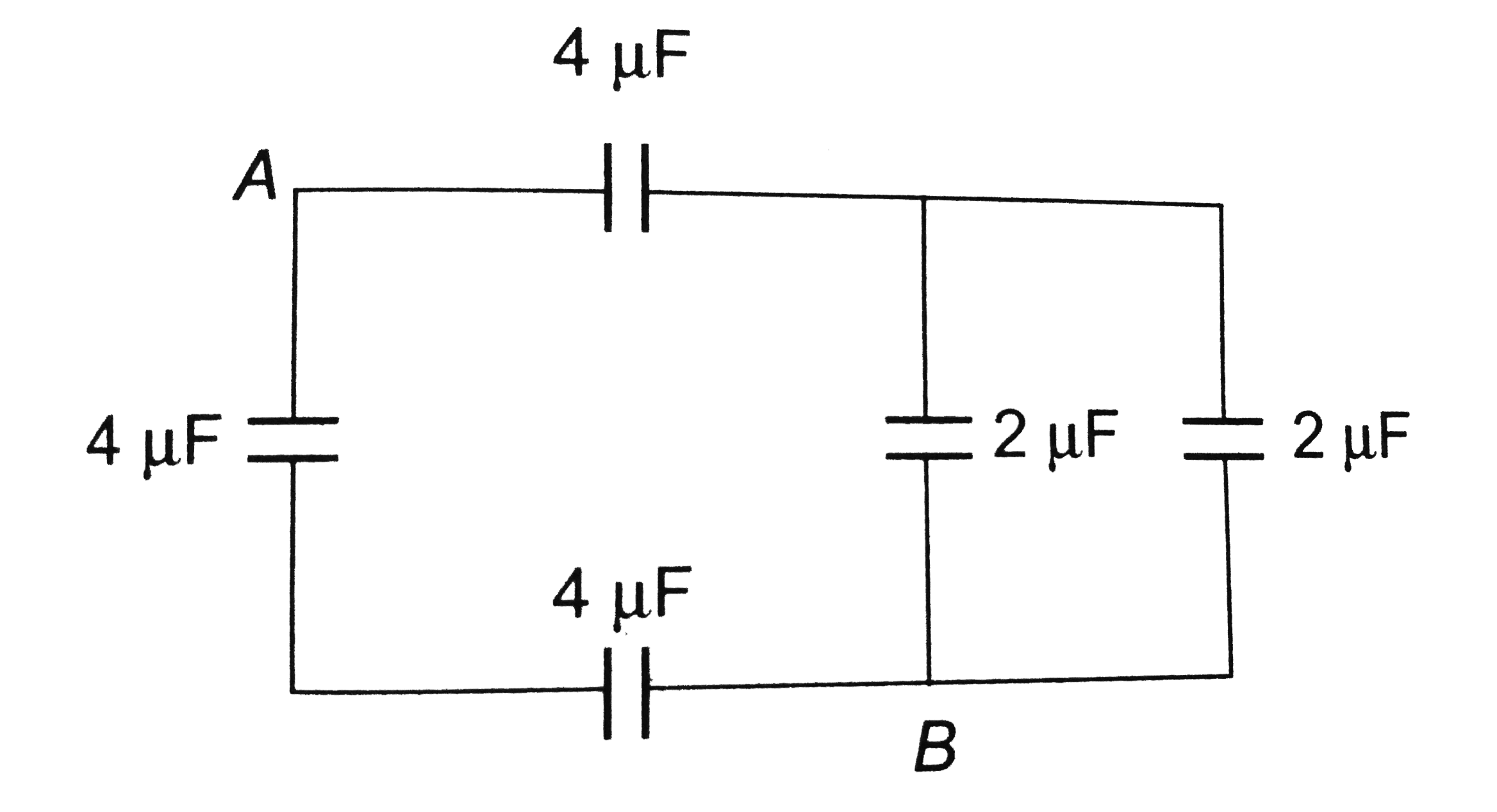
- Equivalent capacitance between A and B is
Text Solution
|
- The energy stored in a capacitor of capacitance 100 muF is 50 J. Its p...
Text Solution
|
- The potential energy of a charged parallel plate capacitor is U(0). If...
Text Solution
|
- A series combination of n(1) capacitors, each of value C(1), is charge...
Text Solution
|
- If the charge on a capacitor is increased by 2C, then the energy store...
Text Solution
|
- A capacitor of capacitance value 1 muF is charged to 30 V and the batt...
Text Solution
|
- A parallel plate capacitor is charged to a potential difference of 50 ...
Text Solution
|