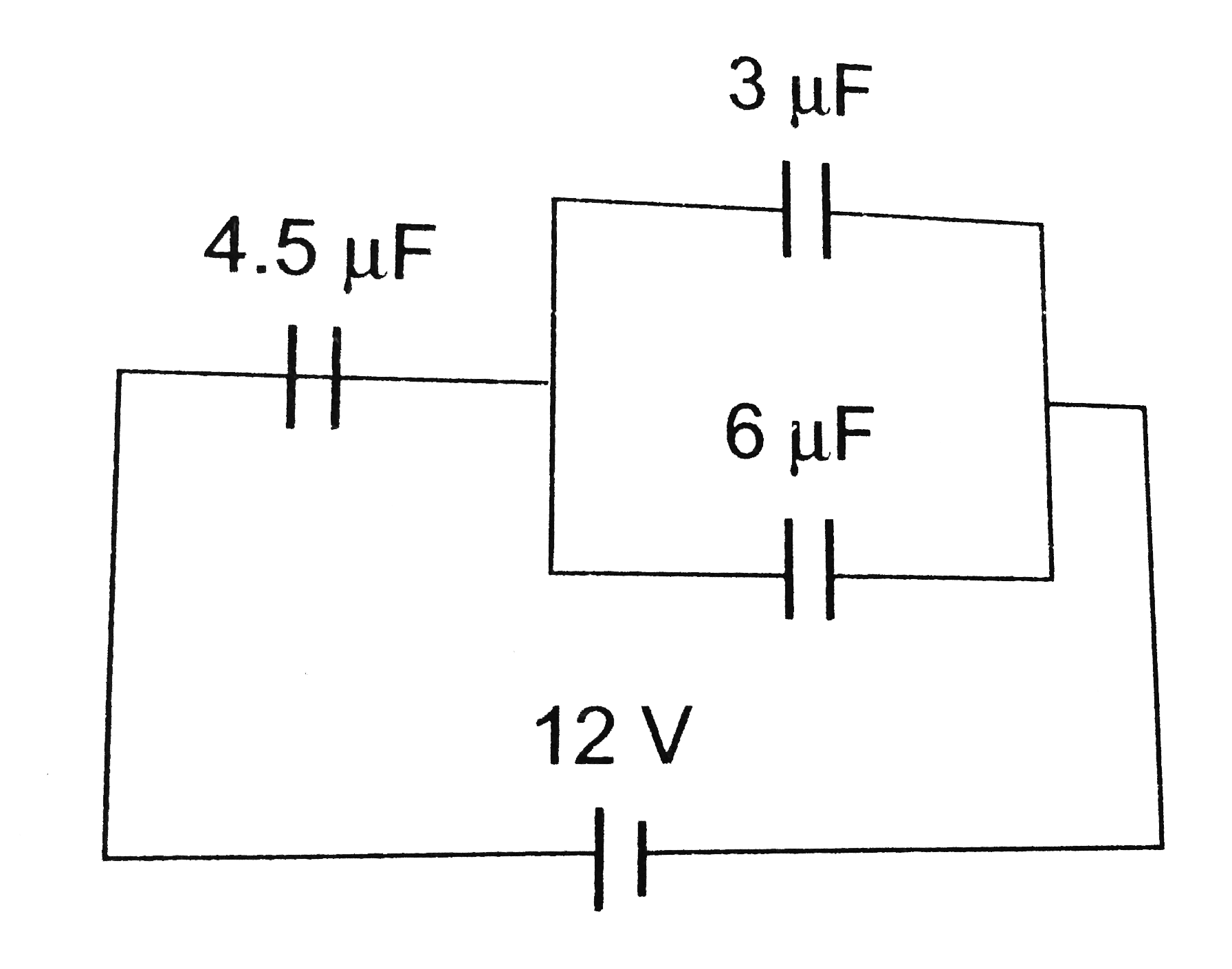
A
B
C
D
Text Solution
Verified by Experts
The correct Answer is:


Topper's Solved these Questions
ELECTROSTATIC POTENTIAL AND CAPACITORS
DC PANDEY|Exercise (B) Chapter exercises|20 VideosELECTROSTATIC POTENTIAL AND CAPACITORS
DC PANDEY|Exercise (C) Chapter exercises|50 VideosELECTROSTATIC POTENTIAL AND CAPACITORS
DC PANDEY|Exercise Check point 2.5|20 VideosELECTROMAGNETIC WAVES
DC PANDEY|Exercise Sec C|22 VideosELECTROSTATICS
DC PANDEY|Exercise Medical entrances gallery|37 Videos
Similar Questions
Explore conceptually related problems
DC PANDEY-ELECTROSTATIC POTENTIAL AND CAPACITORS-(A) Chapter exercises
- The 500 muF capacitor is charged at a steady rate of 100 mu C//s. The ...
Text Solution
|
- A ball of mass 1g and charge 10^(-8) C moves from a point A. Where pot...
Text Solution
|
- In the circuit shown in the figure, the potential difference across th...
Text Solution
|
- Three capacitors of capacitances 1muF,2muF and 4muF are connected firs...
Text Solution
|
- An electron moving with the speed 5xx10^(6) per sec is shot parallel t...
Text Solution
|
- The electirc potential at a point (x, y, z) is given by V = -x^(2)y ...
Text Solution
|
- Three charges -q,+Q and -q are placed in a straight line as shown ...
Text Solution
|
- The mutual electrostatic potential energy between two protons which ar...
Text Solution
|
- Three capacitor of capacitance C(mu F) are connected in parallel to wh...
Text Solution
|
- Figure shows some equipotential lines distributed in space. A charge...
Text Solution
|
- The electrostatic potential on the surface of a charged concducting sp...
Text Solution
|
- Two conducting spheres of radii 3 cm and 1 m are separated by a distan...
Text Solution
|
- Three cahrges each+q, are placed at the corners of an isosceles trinag...
Text Solution
|
- An electric charge 10^-3muC is placed at the origin (0, 0) of X-Y co-o...
Text Solution
|
- Two identicaln thin rings each of radius 10 cm carrying charges 10 C a...
Text Solution
|
- Two equal charges q of opposite sign separated by a distance 2a consti...
Text Solution
|
- The electrostatic potential phi(r), of a spherical symmetrical system ...
Text Solution
|
- An electric dipole when placed in a uniform electric field E will have...
Text Solution
|
- Electric charges of +10 muC,+5 muC,-3 muC and +8 muC are placed at the...
Text Solution
|
- The displacement of a charge Q in the electric field vec(E) = e(1)hat(...
Text Solution
|