


Topper's Solved these Questions
CURRENT ELECTRICITY
DC PANDEY|Exercise Check point|70 VideosCURRENT ELECTRICITY
DC PANDEY|Exercise Taking it together|142 VideosCURRENT ELECTRICITY
DC PANDEY|Exercise Level 2 Subjective|13 VideosCOMMUNICATION SYSTEM
DC PANDEY|Exercise Subjective|11 VideosELECTROMAGNETIC INDUCTION
DC PANDEY|Exercise Medical entrances gallery|25 Videos
Similar Questions
Explore conceptually related problems
DC PANDEY-CURRENT ELECTRICITY-Example
- Find the minimum number of cell required to produce an electron curren...
Text Solution
|
- 36 cells each of internal resistance 0.5 Omega and emf 1.5 V each are ...
Text Solution
|
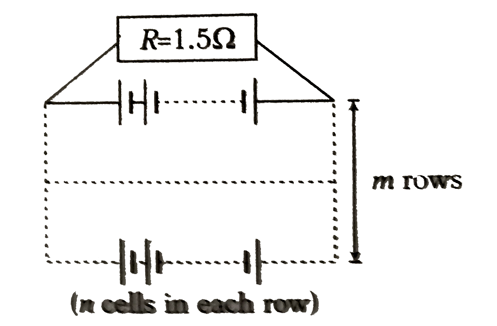
- 12 cells, each of emf 1.5 V and internal resistance of 0.5Omega, are a...
Text Solution
|
- Find currents in different branches of the electric circuit shown in f...
Text Solution
|
- In example above, find the potential difference between points F and C...
Text Solution
|
- (i) Find the potential difference between A and B.
Text Solution
|
- In the circuit shown in figure find the heat developed across each res...
Text Solution
|
- In the circuit shown in the following figure, find
Text Solution
|
- In the following figures, each of the three resistances, the rating of...
Text Solution
|
- Two bulbs having rating of 60 W, 220 V and 100 W, 220 V are joined (i)...
Text Solution
|
- A series circuit consists of three bulbs connected to a battery as sh...
Text Solution
|
- What shunt resistance is required to make the 1.00 mA, 20 Omega Galvan...
Text Solution
|
- How can we make a galvanometer with G=20 Omega and ig=1.0 mA into a vo...
Text Solution
|
- Find out the magnitude of resistance X in the circuit shown in figure,...
Text Solution
|
- Calculate the current the current drawn from the battery by the networ...
Text Solution
|
- In the circuit shown, a meter bridge is in its balanced state. The met...
Text Solution
|
- The figure Shows the experimental set up of a meter bridge. The n...
Text Solution
|
- A potentiometer wire is 10 m long and has a resistance of 18Omega. It ...
Text Solution
|
- A cell can be balanced against 110 cm and 100 cm of potentiometer wire...
Text Solution
|
- In a potentiometer arrangement, a cell of emf 2.25V gives a balance po...
Text Solution
|