A
B
C
D
Text Solution
Verified by Experts
The correct Answer is:


Topper's Solved these Questions
CURRENT ELECTRICITY
DC PANDEY|Exercise B. Assertion and reason|18 VideosCURRENT ELECTRICITY
DC PANDEY|Exercise Match the columns|4 VideosCURRENT ELECTRICITY
DC PANDEY|Exercise Check point|70 VideosCOMMUNICATION SYSTEM
DC PANDEY|Exercise Subjective|11 VideosELECTROMAGNETIC INDUCTION
DC PANDEY|Exercise Medical entrances gallery|25 Videos
Similar Questions
Explore conceptually related problems
DC PANDEY-CURRENT ELECTRICITY-Taking it together
- The resistance across A and B in the figure below will be
Text Solution
|
- The temperature (T) dependence of resistivity (rho) of a semiconductor...
Text Solution
|
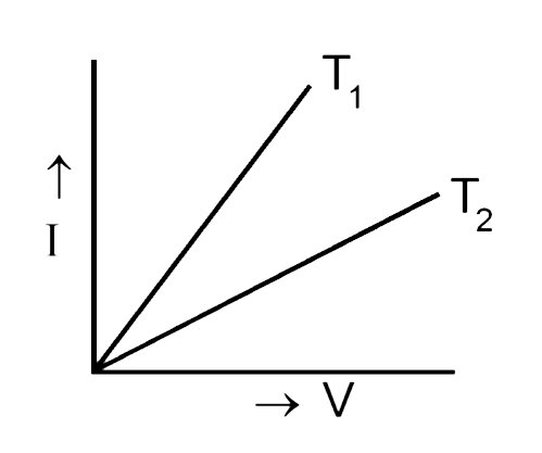
- The current (I) and voltage (V) graphs for a given metallic wire at tw...
Text Solution
|
- Which of the follwing characteristies of electrons determines the curr...
Text Solution
|
- An ammeter and a voltmeter of resistance R connected in seires to an e...
Text Solution
|
- The resistance of a wire is 10 Omega. Its length is increased by 10% b...
Text Solution
|
- Four resistances are connected in a circuit in the given figure. The e...
Text Solution
|
- Current through the 5Omega resistor is
Text Solution
|
- A cell which has an emf 1.5 V is connection series with an external re...
Text Solution
|
- A piece of wire of resistance 4 ohm s is bent through 180^(@) at its...
Text Solution
|
- A wire of resistance R is divided in 10 equal parts. These parts are c...
Text Solution
|
- Three resistors each of 2 ohm are connected together in a triangular s...
Text Solution
|
- The effective resistance between the points A and B in the figure is
Text Solution
|
- Two resistances are joined in parallel whose resultant is 6//8 ohm. On...
Text Solution
|
- A wire of resistanc e9Omega is broken in two parts. The length ratio b...
Text Solution
|
- In the network shown, the equivalent resistance between A and B is
Text Solution
|
- In the circuit shown, the currents i(1) and i(2) are
Text Solution
|
- Consider the following statements regarding the network shown in the f...
Text Solution
|
- To send 10% of the main current through a moving coil galvanometer of ...
Text Solution
|
- A 1250 W heater operates at 115V. What is the resistance of the heatin...
Text Solution
|