Home
Class 12
PHYSICS
A wire is sliding as shown in Figure. Th...

A wire is sliding as shown in Figure. The angle between the acceleration and the velocity of the wire is

A

`30 ^(@)`

B

`40 ^(@)`

C

`120 ^(@)`

D

`90 ^(@)`

Text Solution

Verified by Experts

The correct Answer is:
C

The magetic forec on the wire is perpendicular to wire. (show in the figure )
`therefore" " "Angle"= 30^(@)+ 90^(@)= 120^(@)`
Promotional Banner

Topper's Solved these Questions

  • ELECTRIC CHARGE

    BITSAT GUIDE|Exercise All Questions|28 Videos
  • FLUID MECHANICS

    BITSAT GUIDE|Exercise BITSAT Achives|15 Videos

Similar Questions

Explore conceptually related problems

A horizontal wire carries a current as shown as shown in Figure below between magnetic poles N and S : Is the direction of the force on the wire due to the magnet :

A pearl of mass m is in a position to slide over a smooth wire .At the intial instant the pearl is in the middle of the wire ,The wire moves linerly in a horizontal plane with an with the acceleration of the pearl Q.r.t wire is -

The strain-stress curves of three wire of different materials are shown in the figure. P,Q and R are the elastic limits of the wires. The figures shows that

Consider the situation shown in the figure. The wire Ab is sliding on the fixed rails with a constant velocity. If the wire AB is replaced by semicircular wire, the magnitude of the induced current will

A wire, which passes through the hole in a small bead, is bent in the form of quarter of a circle. The wire is fixed vertically on ground as shown in the figure. The bead is released from near the top of the wire and it slides along the wire without friction. As the bead moves from A to B, the force it applies on the wire is

The strain stress curves of three wires of different materials are shown in the figure. P, Q and R are the elastic limits of the wires. The figure shown that

The strain-stress curves of three wires of different materials ar shown in the figure P,Q and R are the elastic limits of the wires. The figure shows that :

A horizontal wire is free to slide on the verticle rails of a conducting frame as shown in figure. The wire has a mass m and length l and the resistance of the circuit is R . If a uniform magnetic field B is directed perpendicular to the frame, the terminal speed of the wire as it falls under the force of gravity is

A soap film is created in a small wire frame as shown in the figure. The sliding wire of mass m is given a velocity u to the right and assume that u is small enough so that film does not break. Plane of the film is horizontal and surface tension is T, then time to region the original position of wire is equal to :

BITSAT GUIDE-ELECTROMAGNETIC INDUCTION-All Questions
  1. A fan blade of length 2 a rotates with frequency f cycle' per secon...

    Text Solution

    |

  2. A mental rod AB of length l is rotated with a constant angular vel...

    Text Solution

    |

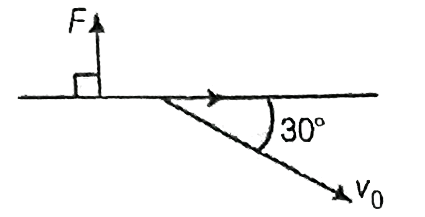
  3. A wire is sliding as shown in Figure. The angle between the accelerati...

    Text Solution

    |

  4. A fan blade of length 1//sqrt(pi) metre rotates with frequncy 5 cy...

    Text Solution

    |

  5. A coil has an area of 0.05m^(2) and has 800 turns . After plac...

    Text Solution

    |

  6. In Fig. a coil of single turn is wound on a sphere of radius r and mas...

    Text Solution

    |

  7. The loop ABCD is moving with velocity 'v' towards right. The magnetic ...

    Text Solution

    |

  8. Calcualte the self-inducatance of the air cored solined of length...

    Text Solution

    |

  9. The inductance per unit length of a double tape line as shown in th...

    Text Solution

    |

  10. What is the mutual inductance of coil and solenid if a has a radiu...

    Text Solution

    |

  11. When the current changes from +2A to -2A in 0.05s, and emf of 8B is in...

    Text Solution

    |

  12. A closed circuit consits of a source of constant and E and a chok...

    Text Solution

    |

  13. Three pure inductors each of 2H are connected as shown in the figure. ...

    Text Solution

    |

  14. The sum and difference of self-inductances of two coils are 13 mH and ...

    Text Solution

    |

  15. In the figure, the steady state current through the inductor will be

    Text Solution

    |

  16. Determine thte valur of time constan for the given circuit

    Text Solution

    |

  17. The time constant for the given circuit is

    Text Solution

    |

  18. With usual notations, the energy dissipation in an ideal inductor is g...

    Text Solution

    |

  19. A non-conducting ring of radius r has charge per unit length lambda. A...

    Text Solution

    |

  20. Figures show a uniform magnetic field B condfirned to ta cylinderical ...

    Text Solution

    |