Home
Class 12
PHYSICS
For the network shown in figure, points ...

For the network shown in figure, points A, B and C are at potentials of 70 V, zero and 10 V respectively

A

point D is at a potential of 40 V

B

the currents in the sections AD, DB and DC are in the ratio `4: 3: 2`

C

the current in the sections AD, DB and DC are in the ratio `1: 2: 3`

D

the network draws a total power of 100 W

Text Solution

Verified by Experts

The correct Answer is:
A

Consider the current distributions in the circuit as shown below

By `KVL, V_(A)-l_(1)10-l_(2)20-V_(B)=0`
`implies l_(1)10+l_(2)20=70`
`V_(A)-l_(1)10-l_(3)30-V_(C )=0`
`implies " " l_(1)10+l_(3)30=60`
Also, `l_(3)=l_(1)-l_(2)`
So, Eq. (ii) becomes
`l_(1)10+30(l_(1)-l_(2))=60`
`l_(1)40-30 l_(2)=60`
Solving Eqs. (i) and (iii), we get
`l_(2)=2 A, l_(1) =3A, l_(3)=1A`
Potential drop across branch AD,
` V_(A)-V_(D)=l_(1)xx10 implies 70-V_(D)=30 implies V_(D)=40 V`
Promotional Banner

Topper's Solved these Questions

  • CURRENT ELECTRICITY

    BITSAT GUIDE|Exercise Bitsat Archives|26 Videos
  • CATHODE RAY, PHOTOELECTRIC EFFECT AND X-RAYS

    BITSAT GUIDE|Exercise BITSAT Archives|6 Videos
  • ELECTRIC CAPACITOR

    BITSAT GUIDE|Exercise BITSAT archives|6 Videos

Similar Questions

Explore conceptually related problems

In the network shown in fig. , points A, B, and C are at potentials of 70 V, 0, and 10V, respectively.

In the circuit given here, the points A,B and C are 70 V, zero, 10 V respectively . Then,

A hollow conducting sphere is placed in an electric field produced by a point charge placed at P as shown in figure. Let V_(A), V_(B), V_(C ) be the potentials at points A, B and C respectively. Then

In the circuit diagram shown in figure, the potentials of the points B, C and D are respectively.

In the circuit diagram shown in Figure , the potentials of the points B, C and D are respectively -

Three uncharged capacitors of capacities C_(1),C_(2) and C_(3) are connected as shown in the figure to one another and the potentials V_(1),V_(2) and V_(3) respectively. Then the potential at O will be .

Three resistance are joined together to form a letter Y, as shown in figure. If the potentials of the terminals A, B and C are 6V, 3V and 2V respectively, then the potential of the point O will be

In the network shown in the figure, the potential difference between A and B is :

BITSAT GUIDE-CURRENT ELECTRICITY-Bitsat Archives
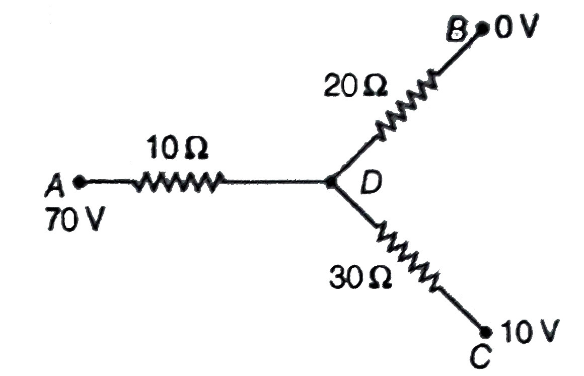
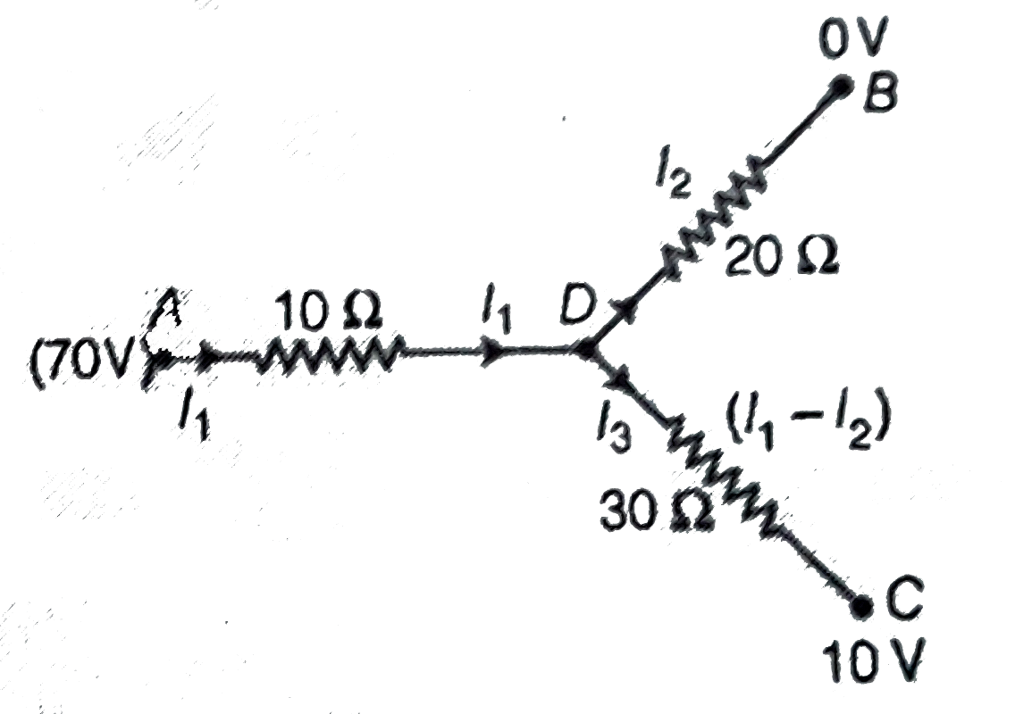
  1. For the network shown in figure, points A, B and C are at potentials o...

    Text Solution

    |

  2. Ohms law says

    Text Solution

    |

  3. A current 4.0 A exist in a wire of cross-sectional area 2.0 mm^(2). If...

    Text Solution

    |

  4. What will be the value of current I in the circuit shown ?

    Text Solution

    |

  5. In the given circuit (as shown in figure), each capacitor has a capaci...

    Text Solution

    |

  6. Three bulbs X, Y and Z are connected as shown in figure. The bulbs Y a...

    Text Solution

    |

  7. In the circuit shown, the value of I in ampere is

    Text Solution

    |

  8. In the circuit shown below, the ammeter reading is zero. Then, the val...

    Text Solution

    |

  9. A steady current flow in a metallic conductor of non-uniform cross-sec...

    Text Solution

    |

  10. Two bulbs which consume powers P(1) " and P(2) are connected in series...

    Text Solution

    |

  11. Three conductors draw respectively currents of 1 A, 2 A and 4 A when c...

    Text Solution

    |

  12. 24 identical cells, each of internal resistance 0.5 Omega, are arrange...

    Text Solution

    |

  13. A wire is stretched as to change its diameter by 0.25%. The percentage...

    Text Solution

    |

  14. If in the circuit shown below, the internal resistance of the battery ...

    Text Solution

    |

  15. When the potential difference applied across a solid conductor is incr...

    Text Solution

    |

  16. A box with two terminals is connected in series with a 2 V battery, an...

    Text Solution

    |

  17. A current of 2 A flows in an electric circuit as shown in figure. The ...

    Text Solution

    |

  18. When a battery connected across a resistor of 16 Omega, the voltage ac...

    Text Solution

    |

  19. If a rod has resistance 4 Omega and if rod is turned as half circle, t...

    Text Solution

    |

  20. In the circuit, the potential difference across PQ will be nearest to

    Text Solution

    |

  21. Each resistance shown in figure is 2 Omega. The equivalent resistance ...

    Text Solution

    |