Home
Class 12
PHYSICS
Three batteries having emfs and internal...

Three batteries having emfs and internal resistances as shown in figure are connected across a resistor of `2Omega`. The reading of ammeter is

A

1A

B

1.5A

C

2A

D

2.5A

Text Solution

Verified by Experts

The correct Answer is:
A

Use `(E_(eq))/(R_(eq)) = E_1/R_1+E_2/R_2+E_3/R_3+…..`
The circuit can be redrawn as

`1/r_(eq) = 1/2+1/2+1/1`
`r_(eq) = 1/2 Omega`
`(E_(eq))/(1/2) = 10/2+10/2-5/1`
`E_(eq) = 10/4 = 2.5 V`
`i=(2.5)/(2.5) = 1A`
Promotional Banner

Topper's Solved these Questions

  • MAJOR TEST 9

    NEET MAJOR TEST (COACHING)|Exercise PHYSICS|44 Videos
  • NEET DRILL 3

    NEET MAJOR TEST (COACHING)|Exercise PHYSICS|45 Videos

Similar Questions

Explore conceptually related problems

A battery of emf 2V and internal resistance 0.5(Omega) is connected across a resistance in 1 second?

A battery having e.m.f. 5 V and internal resistance 0.5 Omega is connected with a resistance of 4.5 Omega then the voltage at the terminals of battery is

A battery of emf 1.4 V and internal resistance 2 Omega is connected to a resistor of 100 omega resistance through an ammeter. This resistance of the ammeter is 4//3 Omega . A voltmeter has also been connected to find the potential difference across the resistor. a. Draw the circuit diagram. b. The ammeter reads 0.02 A . What is the resistance of the voltmeter? c. The voltmeter reads 1.1 V . What is the error in the reading?

The potential dofference between the terminals of a battery of emf6.0V and internal resistances 1 (Omega) drops it 5.8 V when connected across an external resistor. Find the resistance of the external resistor.

A battery of emf 2 V and internal resistance r is connected in series with a resistor of 10Omega through an ammeter of resistance 2Omega . The ammeter reads 50 mA. Draw the circuit diagram and calculate the value of r.

A battery of emf 3V and internal resistance r is connected in series with a resistor of 55 Omega through an ammeter of resistance 1 Omega . The ammeter reads 50 mA. Draw the circuit diagram and calculate the value of r.

A battery of emf 3 volt and internal resistance r is connected in series with a resistor of 55 Omega through an ammeter of resistance 1 Omega . The ammeter reads 50 mA. Draw the circuit diagram and calculate the value of r.

NEET MAJOR TEST (COACHING)-NEET 2020 TEST 5-PHYSICS
  1. A circuit is shown in the figure. The ratio of readings of ideal voltm...

    Text Solution

    |

  2. A 6A fuse wire can withstand a maximum power of 18W in circuit . The r...

    Text Solution

    |

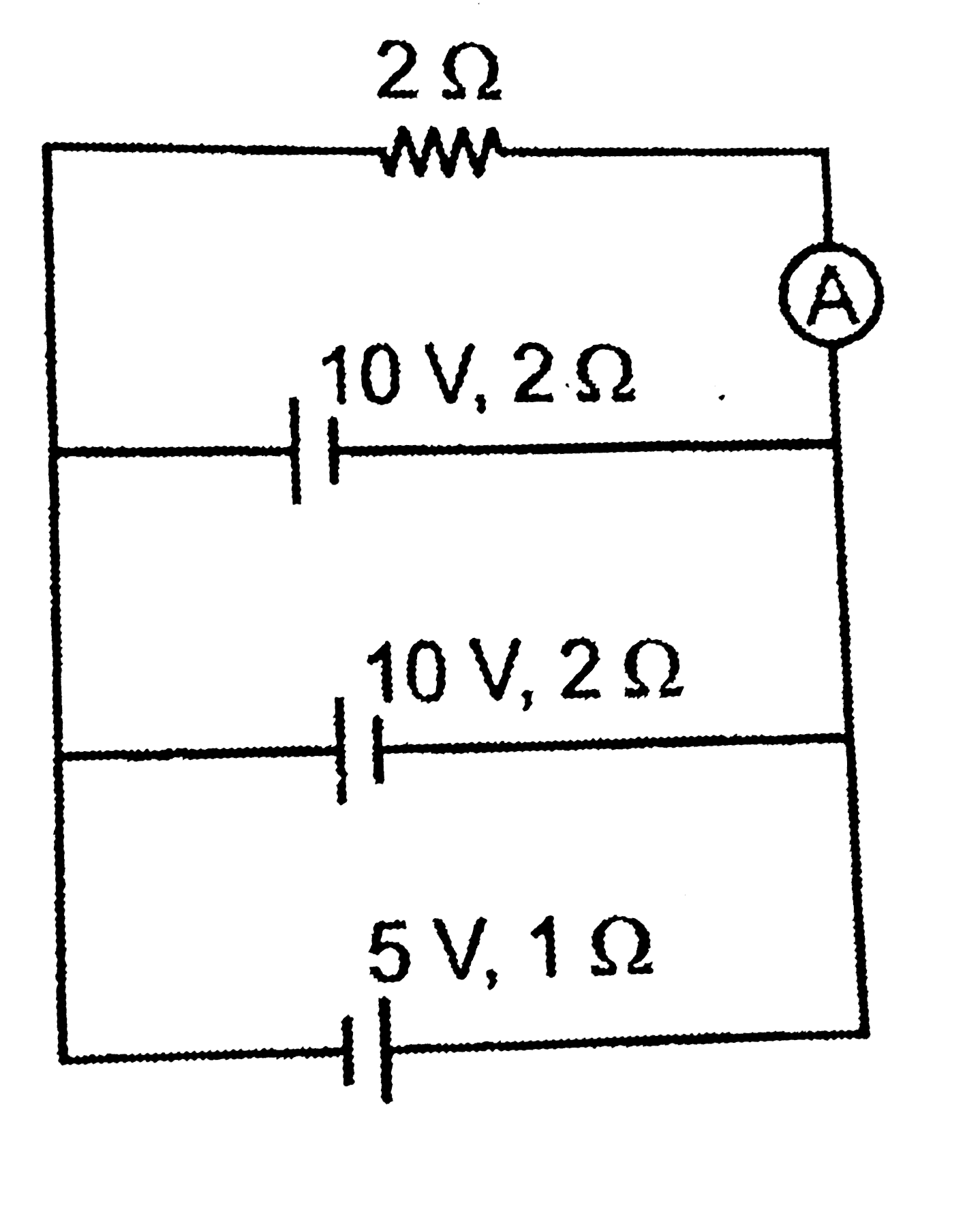
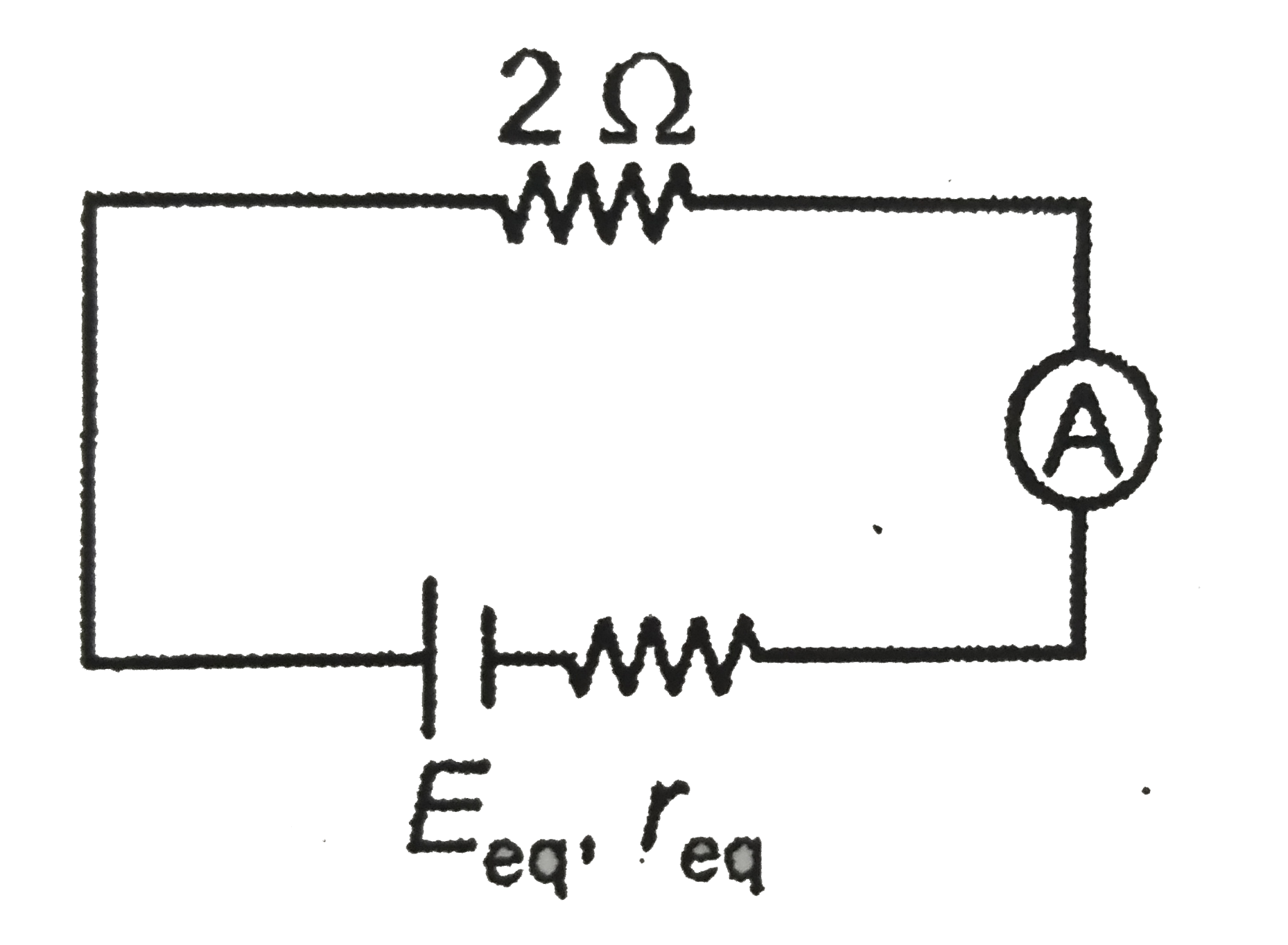
  3. Three batteries having emfs and internal resistances as shown in figur...

    Text Solution

    |

  4. Two metal rods are joined end to end, as shown in the figure . Both ha...

    Text Solution

    |

  5. In a metre bridge , the balancing length from the left end is found to...

    Text Solution

    |

  6. In the given potentiometer circuit , internal resistance r of the cell...

    Text Solution

    |

  7. A filament bulb (400W, 100V ) is to be used in a 230V main supply . Wh...

    Text Solution

    |

  8. A electrical circuit is shown in the figure. The value of current I pa...

    Text Solution

    |

  9. The power dissipated in 3Omega resistor in the circuits as shown in th...

    Text Solution

    |

  10. In the circuit shown in the figure, if potentail at point A is taken t...

    Text Solution

    |

  11. Two cities are 200km apart. Electric power is sent from one city to an...

    Text Solution

    |

  12. The potential difference (VA-VB) between the point A and B as shown in...

    Text Solution

    |

  13. The resistance of wire is 100Omega . If it is stretched to 4 times its...

    Text Solution

    |

  14. A potentiometer wire has length 8m and resistance 16Omega . The resist...

    Text Solution

    |

  15. A carbon resistor of (12pm1.2)kOmega is to be marked with rings of dif...

    Text Solution

    |

  16. For the given conductor the drift speed of electrons at cross section ...

    Text Solution

    |

  17. The value of R in the circuit shown in the figure is

    Text Solution

    |

  18. In the circuit shown in the figure , if a conducting wire is conneted ...

    Text Solution

    |

  19. Consider the following statements: Statement (I) : Kirchoff's juctio...

    Text Solution

    |

  20. A condcuting slab of thickness d/2 is inserted between the plates of p...

    Text Solution

    |