A
B
C
D
Text Solution
Verified by Experts
The correct Answer is:


Topper's Solved these Questions
Similar Questions
Explore conceptually related problems
NEET MAJOR TEST (COACHING)-NEET 2020 TEST 5-PHYSICS
- A condcuting slab of thickness d/2 is inserted between the plates of p...
Text Solution
|
- For the arrangement shown in the figure, the charge on the 4muF capac...
Text Solution
|
- Five capacitors each of capacitance C and breakdown voltage V are conn...
Text Solution
|
- Eight capacitors , each of capacitance 2muF are conneted as shown in t...
Text Solution
|
- An electric dipole moment p is aligned parallel to a uniform electric ...
Text Solution
|
- Five capacitors are connected in series as shown in figure with a batt...
Text Solution
|
- Two point charge qA " and " qB are placed in a uniform external electr...
Text Solution
|
- A large number of particles each having electric charge 1muC are place...
Text Solution
|
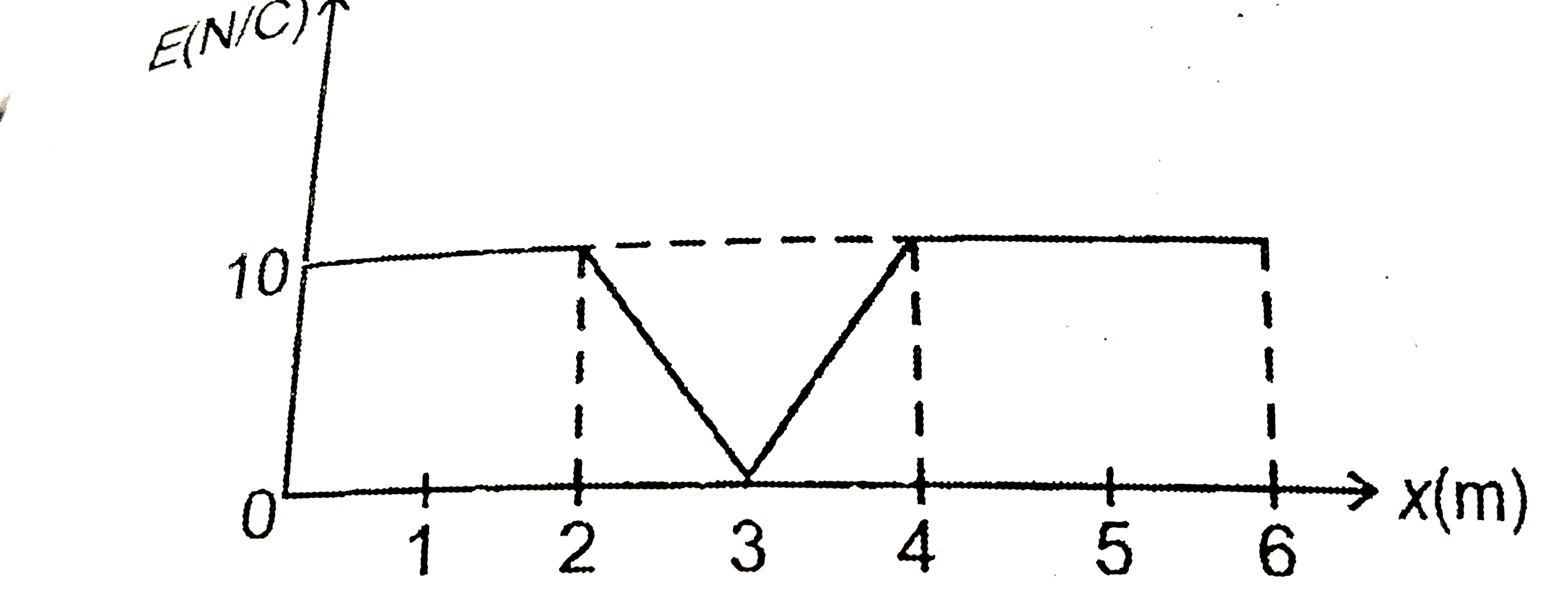
- Figure shows the variation of electric field intensity E with distance...
Text Solution
|
- Figure shows a set of equipotential surfaces. The magnitude and direct...
Text Solution
|
- The electric potential at a point (x, y, z) is given by V=-xy+z-z^3yx ...
Text Solution
|
- Two point charges +q and -q are placed at point A and B respectively w...
Text Solution
|
- A, B and C are three points in an electrostatics field. The electric p...
Text Solution
|
- Three point charges are placed as shown in the figure. S is a gaussian...
Text Solution
|
- A very long uniformly charged thin wire whose one end is at point (0,...
Text Solution
|
- Three point charges 1muC ,1muC " and " -2muC are placed at points havi...
Text Solution
|
- A point object of mass 1mg and charge 1muC is hung with a silk thread ...
Text Solution
|
- Four point charges q, -2q, -q and 2q are placed at points (0,0,0) m , ...
Text Solution
|
- A charge 4muC is located at the centre of one of the edge of a cube . ...
Text Solution
|
- A particle of mass m and charge q is placed at rest in a uniform elect...
Text Solution
|