A
B
C
D
Text Solution
Verified by Experts
The correct Answer is:


Topper's Solved these Questions
SEMI CONDUCTOR AND LOGIC GATES
MOTION|Exercise EXERCISE 3|34 VideosSEMI CONDUCTOR AND LOGIC GATES
MOTION|Exercise EXERCISE 3|34 VideosROTATIONAL MOTION
MOTION|Exercise Exercise - 3 ( Section-B )|24 VideosSIMPLE HARMONIC MOTION
MOTION|Exercise EXERCISE -3 Section - B Previous Year Problems | JEE MAIN|23 Videos
Similar Questions
Explore conceptually related problems
MOTION-SEMI CONDUCTOR AND LOGIC GATES-EXERCISE 2
- Two identical p-n junctions may be connected in series in which a batt...
Text Solution
|
- In the figure an A.C of rms voltage 200 volt is appled to the circuit ...
Text Solution
|
- Which of the following statements is wrong ?
Text Solution
|
- If the following input signal is sent through a P-N junction diode, th...
Text Solution
|
- The value of current in the following diagram will be –
Text Solution
|
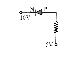
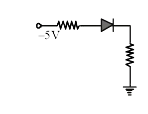
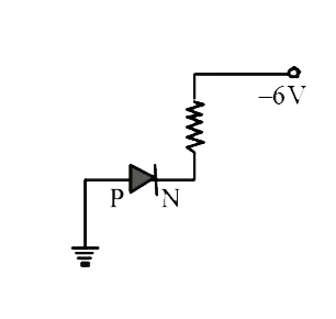
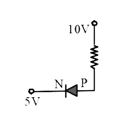
- In which of the following figure the junction diode is reverse biased ...
Text Solution
|
- Two identical capacitors A and B are charged to the same potential V a...
Text Solution
|
- In the circuit shown in figure, Voltage V0 is–
Text Solution
|
- Determine current I in the configuration –
Text Solution
|
- In the given circuit V(01) " and " V(02) are -
Text Solution
|
- A cube of germanium is placed between the poles of a magnet and a volt...
Text Solution
|
- A full wave rectifier circuit along with the output is shown in the fo...
Text Solution
|
- In the given figure potential difference between A and B is -
Text Solution
|
- In figure the current supplied by the battery is -
Text Solution
|
- In a p-n junction
Text Solution
|
- The temperature coefficient of resistance of a semiconductor
Text Solution
|
- A piece of copper and another of germanium are cooled from room temper...
Text Solution
|
- Consider an n-p-n transistor amplifer in common-emitter configuration....
Text Solution
|
- In a semiconducting material the mobilities of electrons and holes are...
Text Solution
|
- In a transistor the base is very lightly doped as compared to the emit...
Text Solution
|