Home
Class 12
PHYSICS
in the figure shown , a circuit contai...

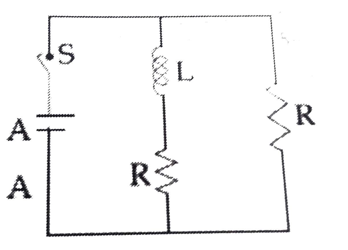
in the figure shown , a circuit contains two identical resistors with resistance `R= Omega` and an inductance with L=2 H ,An ideal battery of 15 V is connected in the circuit what will be the current through the battery long after the switch is clossed ?

Text Solution

Verified by Experts

The correct Answer is:
6

`I=(15)/(2.5)=6`
Promotional Banner

Similar Questions

Explore conceptually related problems

In the circuit diagram the current through the battery immediately after the switch S is closed is

Consider the circuit shown in figure. The current through the battery a long time after the switch S is closed is:

Figure shows a circuit that contains three identical resistors with reisistance R=9.0 Omega each, two identical inductors with inductance L=2.0mH each, and an ideal battery with emf e= 18V . The current I through th battery just after the switch closed is

Figure shows a circuit that contains three identical resistors with resistance R=0.9 Omega each, two identical inductors with inductance L=2.0 mH each, and an ideal battery with emf epsilon=18 V . The current i through the battery just after the switch closed is.......:

Figure shows a circuit that contains three identical resistors with resistance R = 9.0 Omega each, two identical inductors with inductance L = 2.0 mH each, and an ideal battery with emf epsilon = 18 V. The current "i" through the battery just after the switch closed is, .......

A circuit that contains three identical resistors with resistance R = 9.0 Omega each, two identical inductors with inductance L = 2.0 mH each, and an ideal battery with emf epsilon = 18 V . The current 'i' through the battery just after the switch closed

Figure shows a circuit that contains four identical resistors with resistance R = 2.0 Omega , two identical inductors with inductance L = 2.0 mH and an ideal battery with emf E = 9 V. The current 'i' just after the switch 'S' is closed will be :

Current through the battery in the circuit shown in the figure

The figure shows three circuit with identical batteries, inductors and resistance. Rank the circuit according to the currents through the battery just after the switch is closed greatest first :