Text Solution
Verified by Experts
The correct Answer is:


Similar Questions
Explore conceptually related problems
Recommended Questions
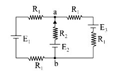
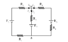
- For the circuit shown, with R1=1.0 Omega,R2=2.0Omega,E1=2V and E2=E3...
Text Solution
|
- In the circuit shown in figure E1=10 V, E2=4V, r1=r2=1Omega and R=2Ome...
Text Solution
|
- In the circuit in figure E1=3V, E2=2V, E3=1V and R=r1-r2-r3=1Omega a. ...
Text Solution
|
- In the following circuit ,E1 = 4V, R1 = 2 Omega, E2 = 6 V, R2 = 2Oem...
Text Solution
|
- In the circuit shown in fig. 5.265, E1 = E2 = E3 = 2V and R1 = R2 = 4O...
Text Solution
|
- For the batteries shown in fig. R1, R2 and R3 are the internal resista...
Text Solution
|
- For the circuit shown, with R1=1.0 Omega,R2=2.0Omega,E1=2V and E2=E3...
Text Solution
|
- यहाँ दर्शाये गये परिपथ में E1 = E2 = E3 = 2 वोल्ट तथा R1= R2 =4 Omega ...
Text Solution
|
- For the circuit shown, with R1=1.0Omega, R2=2.0Omega, E1=2V and E2=E3=...
Text Solution
|