A
B
C
D
Text Solution
Verified by Experts
The correct Answer is:


Topper's Solved these Questions
MOTION-Capacitance -EXERCISE -1
- Three uncharged capacitors of capacitane C1 = 1muF, C2 = 2muF and C3 =...
Text Solution
|
- Five capacitors are connected as shown in the figure. Initially S is o...
Text Solution
|
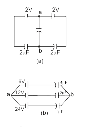
- Find the potential difference Va – Vb between the points a and b shows...
Text Solution
|
- Each plate of a parallel -plate air capacitor has an area S. What amou...
Text Solution
|
- the voltage across the capacitor, which is equal to V, is kept constan...
Text Solution
|
- If charge on left plane of the 5muF capacitor in the circuit segment s...
Text Solution
|
- In the circuit shown, the energy stored in 1mu F capacitor is
Text Solution
|
- A capacitor C(1)=4muF is connected in series with another capaciitor C...
Text Solution
|
- In the circuit shown in figure, the ratio of charges on 5 muF and 4 mu...
Text Solution
|
- In the circuit shown, a potential difference of 60V is applied across ...
Text Solution
|
- Find the equivalent capacitance across A & B
Text Solution
|
- An infinite number of identical capacitors each of capacitance 1 muF ...
Text Solution
|
- Three large plates are arranged as shown. How much charge will flow th...
Text Solution
|
- Five conduting parallel plates having area A and separation between th...
Text Solution
|
- Five identical capacitor plates are arranged such that they make four ...
Text Solution
|
- Consider the situation shown in figure (31-E23 ) . The switch S is ope...
Text Solution
|
- Consider the situation shown in the figure. The switch S is open for ...
Text Solution
|
- Consider the situation shown in the figure. The switch S is open for ...
Text Solution
|
- Consider the situation shown in the figure. The switch S is open for ...
Text Solution
|
- The diagram shown four capacitors with capacitances and break down vol...
Text Solution
|