A
B
C
D
Text Solution
Verified by Experts
The correct Answer is:


Topper's Solved these Questions
Similar Questions
Explore conceptually related problems
MOTION-Capacitance -EXERCISE -1
- In the circuit shown, the energy stored in 1mu F capacitor is
Text Solution
|
- A capacitor C(1)=4muF is connected in series with another capaciitor C...
Text Solution
|
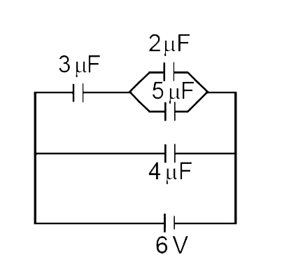
- In the circuit shown in figure, the ratio of charges on 5 muF and 4 mu...
Text Solution
|
- In the circuit shown, a potential difference of 60V is applied across ...
Text Solution
|
- Find the equivalent capacitance across A & B
Text Solution
|
- An infinite number of identical capacitors each of capacitance 1 muF ...
Text Solution
|
- Three large plates are arranged as shown. How much charge will flow th...
Text Solution
|
- Five conduting parallel plates having area A and separation between th...
Text Solution
|
- Five identical capacitor plates are arranged such that they make four ...
Text Solution
|
- Consider the situation shown in figure (31-E23 ) . The switch S is ope...
Text Solution
|
- Consider the situation shown in the figure. The switch S is open for ...
Text Solution
|
- Consider the situation shown in the figure. The switch S is open for ...
Text Solution
|
- Consider the situation shown in the figure. The switch S is open for ...
Text Solution
|
- The diagram shown four capacitors with capacitances and break down vol...
Text Solution
|
- Three capacitors 2 mu F, 3 muF and 5 muF can withstand voltages to 3 V...
Text Solution
|
- A metallic plate of thickness (t) and face area of one side (A) is in...
Text Solution
|
- Two metal plates form a parallel plate condenser. The distance between...
Text Solution
|
- The distance between plates of a parallel plate capacitor is 5d. Let t...
Text Solution
|
- A parallel plate capacitor has two layers of dielectric as shown in fi...
Text Solution
|
- The parallel plates of a capacitor have an area 0.2 m^2 and are 10^(–2...
Text Solution
|