A
B
C
D
Text Solution
Verified by Experts
The correct Answer is:


MOTION-Capacitance -EXERCISE -4 LEVEL II
- In the given circuit, the switch S is closed at time t = 0 . The charg...
Text Solution
|
- An uncharged capacitor of capacitance 4mu f , a battery of emf 12 volt...
Text Solution
|
- Given : R1 =1ohm, R2 = 2ohm, C1 = 2 muF, C2 = 4muF The time consta...
Text Solution
|
- A circuit is connected as shown in the figure with the switch S open. ...
Text Solution
|
- A parallel plate capacitor C with plates of unit area and separation d...
Text Solution
|
- At time t=0, a battery of 10 V is connected across points A and B in t...
Text Solution
|
- A 2muF capacitor is charged as shown in the figure. The percentage of ...
Text Solution
|
- In the given circuit, a charge of +80muC is given to the upper plate o...
Text Solution
|
- In the circuit shown in the figure, there are two parallel plate capac...
Text Solution
|
- A parallel plate capacitor has a dielectric slab of dielectric constan...
Text Solution
|
- At time t = 0, terminal A in the circuit shown in the figure is connec...
Text Solution
|
- A parallel plate capacitor having plates of area S and plate separatio...
Text Solution
|
- A combination of capacitors is set up as shown in the figure. The magn...
Text Solution
|
- Consider an evacuted cylindrical chamber of height h having rigid cond...
Text Solution
|
- Consider an evacuted cylindrical chamber of height h having rigid cond...
Text Solution
|
- In process 2, total energy dissipated across the resistance ED is -
Text Solution
|
- In process 1, the energy stored in the capacitor EC and heat dissipate...
Text Solution
|
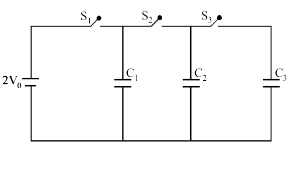
- Three identical capacitors C(1),C(2) and C(3) have a capacitance of 1...
Text Solution
|
- A parallel plate capacitor of capacitance C has spacing d between two ...
Text Solution
|