Home
Class 12
PHYSICS
Correct diagram for the determination of...

Correct diagram for the determination of internal resistance of a primary cell by potentiometer

A

B

C

D

None of the above

Text Solution

AI Generated Solution

The correct Answer is:
To determine the internal resistance of a primary cell using a potentiometer, we can follow these steps to set up the correct circuit diagram and understand its functioning: ### Step-by-Step Solution 1. **Understand the Components**: - Identify the components needed: a primary cell (whose internal resistance we want to measure), a potentiometer, a galvanometer, a known resistor (external resistance), and a battery. 2. **Connect the Circuit**: - Connect the positive terminal of the primary cell to one end of the potentiometer wire. - Connect the negative terminal of the primary cell to the negative terminal of the battery. - Connect the positive terminal of the battery to the other end of the potentiometer wire. 3. **Insert the Galvanometer**: - Connect the galvanometer in parallel with the potentiometer wire. This will help in detecting the null point where no current flows through the galvanometer. 4. **Add the External Resistance**: - Include a known external resistance in series with the primary cell. This will allow us to measure the current flowing through the circuit. 5. **Adjust for Null Point**: - Adjust the position of the sliding contact on the potentiometer wire until the galvanometer shows zero deflection (null point). This indicates that the potential difference across the galvanometer is zero. 6. **Measure the Voltage**: - At the null point, measure the length of the potentiometer wire that corresponds to the potential difference across the known resistor. Use the formula \( V = k \cdot L \), where \( V \) is the voltage, \( k \) is the potential gradient of the potentiometer, and \( L \) is the length of the wire. 7. **Calculate Internal Resistance**: - Use Ohm's law and the known values to calculate the internal resistance \( r \) of the primary cell using the formula: \[ r = \frac{E - V}{I} \] where \( E \) is the electromotive force (emf) of the cell, \( V \) is the voltage across the external resistor, and \( I \) is the current through the circuit.
Promotional Banner

Topper's Solved these Questions

  • Electrical Instrument

    MOTION|Exercise EXERCISE -2|21 Videos
  • Electrical Instrument

    MOTION|Exercise EXERCISE -3|16 Videos
  • Electrical Instrument

    MOTION|Exercise EXERCISE -3|16 Videos
  • ELASTICITY AND THERMAL EXPANSION

    MOTION|Exercise Exercise - 4 (Level-II)|11 Videos
  • ELECTRO MAGNETIC INDUCTION

    MOTION|Exercise EXERCISE-4| Section B (Prevous Years Problems )|29 Videos
MOTION-Electrical Instrument -EXERCISE -1
  1. Potentiometer is an ideal instrument because

    Text Solution

    |

  2. A potentiometer works on the principle that

    Text Solution

    |

  3. If the length of potentiometer wire is increased, then the accuracy in...

    Text Solution

    |

  4. In an ammeter calibration experiment, the potentiometer is used to mea...

    Text Solution

    |

  5. In potentiometer the potential gradient is –

    Text Solution

    |

  6. If the potentiometer wire having resistance rho ohm/ m and I amp. curr...

    Text Solution

    |

  7. Discuss the principle of potentiometer and explain the determination o...

    Text Solution

    |

  8. The material of wire of potentiometer is

    Text Solution

    |

  9. If the current in the primary circuit of a potentiometer wire of speci...

    Text Solution

    |

  10. The p.d. between A and B is balanced at 2.036 m length of the potentio...

    Text Solution

    |

  11. In the following figure, the p.d. between the points M and N is balanc...

    Text Solution

    |

  12. In the foregoing question, the balancing length between the p.d. betwe...

    Text Solution

    |

  13. In a potentiometer of one meter length , an unknown emf voltage source...

    Text Solution

    |

  14. The voltage across the two equal resistances connected in series get b...

    Text Solution

    |

  15. The quantity that cannot be measured by a potentiometer is….

    Text Solution

    |

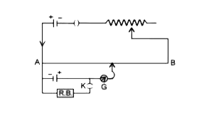
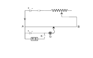
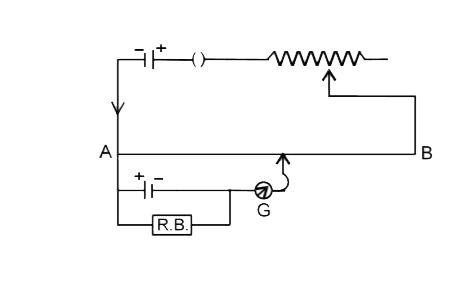
  16. Correct diagram for the determination of internal resistance of a prim...

    Text Solution

    |

  17. A potentiometer has uniform potential gradient across it. Two cells c...

    Text Solution

    |

  18. A wire connected in the left gap of a meter bridge balance a 10Omega r...

    Text Solution

    |

  19. With two resistance R1 and R2 (>R1) in the two gaps of a metre bridge ...

    Text Solution

    |

  20. In a simple meter bridge circuit, the gaps are bridged by cord P and Q...

    Text Solution

    |