A
B
C
D
Text Solution
Verified by Experts
The correct Answer is:


Similar Questions
Explore conceptually related problems
Recommended Questions
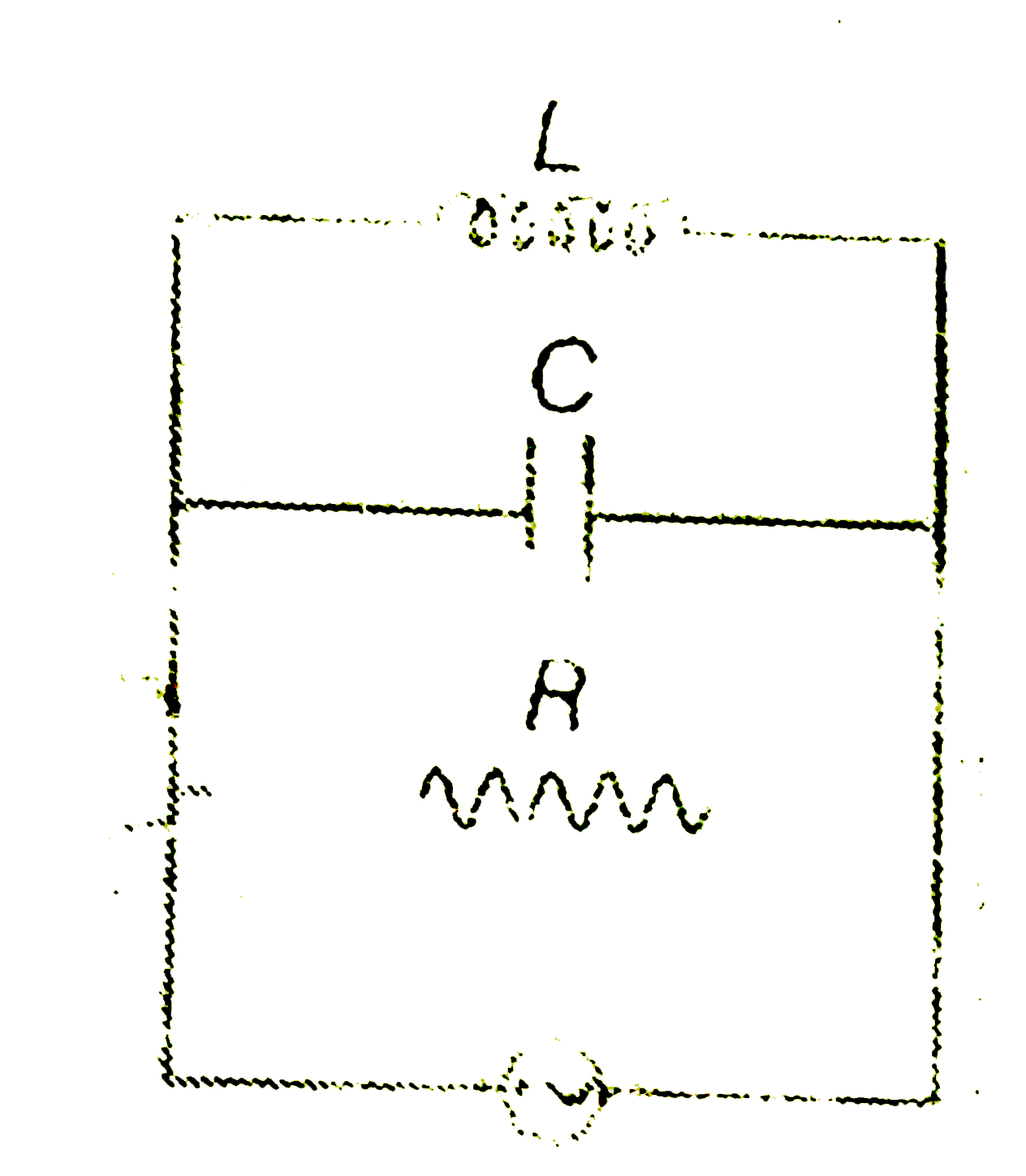
- Figures shows a parallel LCR circuit connected to a 200V, AC source. L...
Text Solution
|
- Figure shows an LCR circuit. When the switch is closed, the currents t...
Text Solution
|
- Figures shows a parallel LCR circuit connected to a 200V, AC source. L...
Text Solution
|
- A L-C-R circuit with L=1.00 mH, C= 10 muF and R=50Omega , is driven wi...
Text Solution
|
- A series LCR circuit is connected to a variable frequency 230 V source...
Text Solution
|
- A series LCR circuit is connected to a variable frequency 230 V source...
Text Solution
|
- A series LCR circuit is connected to a variable frequency 230 V source...
Text Solution
|
- An LCR circuit (R=40Omega,L=100mH,C=0.242muF) is connected with an ac ...
Text Solution
|
- चित्र में एक श्रेणीबद्ध LCR परिपथ दिखलाया गया है जिसे परिवर्ती आवृत्ति...
Text Solution
|