Home
Class 12
PHYSICS
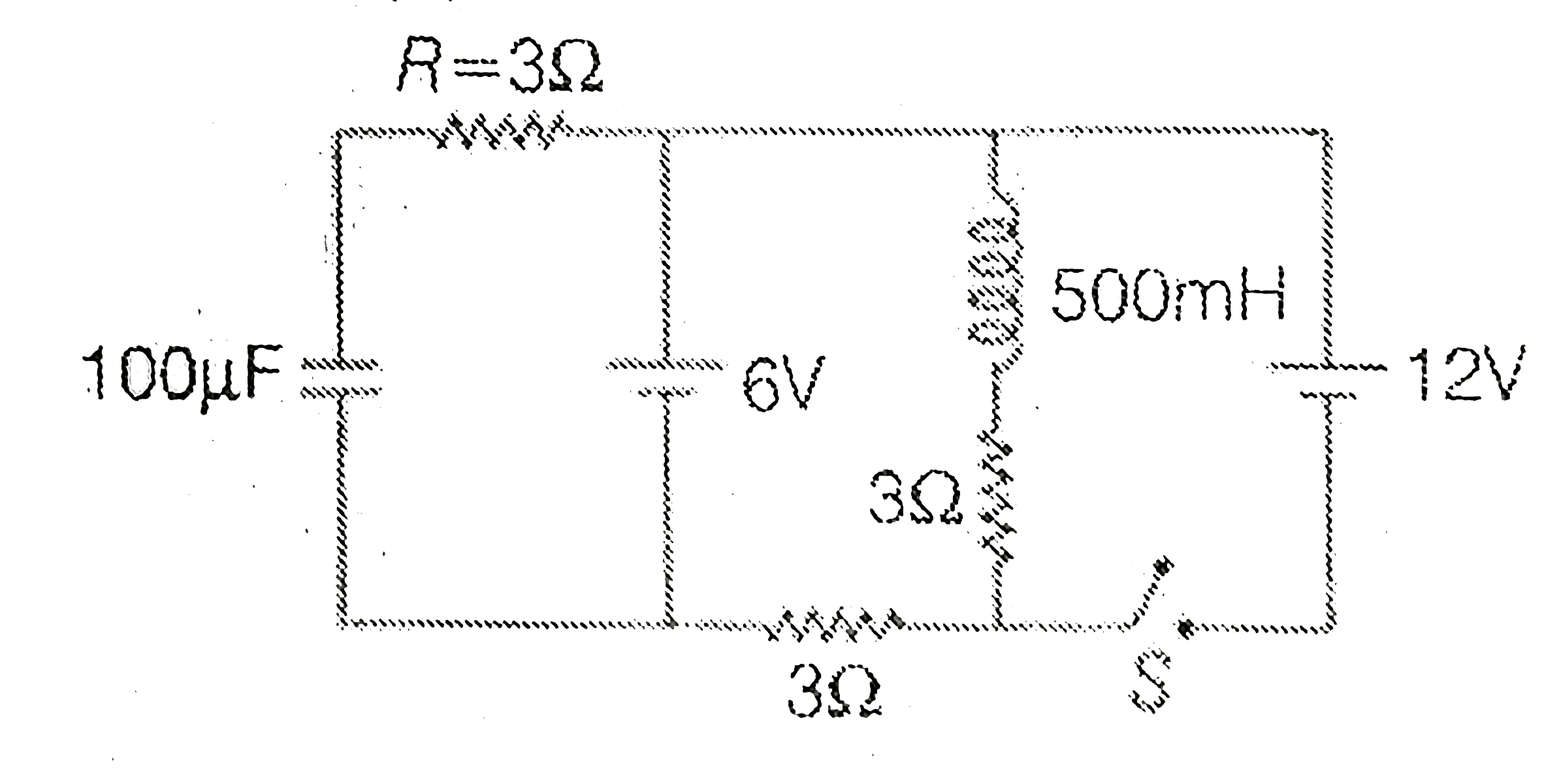
In the circuit diagram shown in figure, ...

In the circuit diagram shown in figure, initially switch S is opened and the circuit is in steady state. At time t=0, the switch S is closed and the new steady state is reached after some time. Choose the correct option(s)

A

Current in the indcutor when the circuit reaches the new steady state is 4A.

B

The net change in the magnitic flux is the inductor is 1.5Wb

C

The net change in the magnetic flux in the conductor is 9volt when the circuit reaches the new steady state.

D

The charge stored in the capacitor in the new steady state is 1.2mC

Text Solution

Verified by Experts

The correct Answer is:
A, B
Doubtnut Promotions Banner Mobile Dark
|

Similar Questions

Explore conceptually related problems

In the circuit as shown in figure the switch is closed at t = 0 . A long time after closing the switch

In the circuit shown in fig, if the switch S is closed at t = 0 , the capacitor charges with a time constant

Knowledge Check

  • In the circuit as shown in the figure, switch S is added at t=0. Then:

    A
    after a long time interval potential differences across capacitor and inductor will be equal
    B
    after a long time interval charge on a capacitor will be EC
    C
    after a long time interval curent in the inductory will be E/R
    D
    after a long time interval current through battery willl be same as the curren through it initially
  • In the circuit shown in figure, switch S is initially closed and S is open. Find V-V

    A
    `4V`
    B
    `8V`
    C
    `12V`
    D
    `16V`
  • In the circuit as shown in figure the switch is closed at t = 0 . At the instant of closing the switch

    A
    the battery delivers maximum current
    B
    no current flows through `C`
    C
    voltage drop across `R_(2)` is zero
    D
    the current through the battery decreases with time finally becomes zero
  • Similar Questions

    Explore conceptually related problems

    In the circuit shown in the figure, switch S is closed at time t=0 . Select the correct statements.

    In the circuit shown in figure initially the switch is opened. The switch is closed now. The charge that will flow in direction 2 is

    In the circuit shown in figure initially the switch is opened. The switch is closed now. The charge that will flow in direction 1 is

    The circuit consists of two resistors (of resistance R_(1) = 20 Omega and R_(2) = 10 Omega ), a capacitor (of capacitance C =10 muF ) and two ideal cells. In the circuit shown the capacitor is in steady state and the switch S is open the circuit is in steady state with switch S closed. Now the switch S is opened. Just after the switch S is opened. the current through resistance R_(1) is

    In the circuit shown in figure switch S is closed at time t=0 Current I from the battery at time t is given by