Home
Class 12
PHYSICS
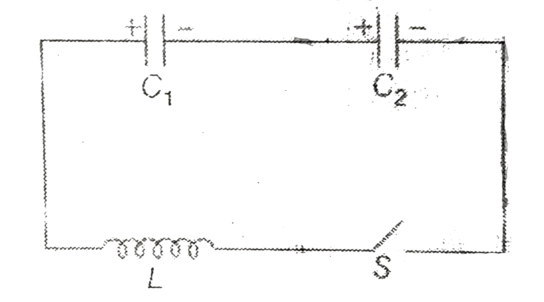
In the figure shown C(1)=1F, C(2)=2F and...

In the figure shown `C_(1)=1F, C_(2)=2F and L=5H`. Initially `C_(1)` is charged 50V and `C_(2)` to 10V. Switch S is closed at time t=D. Suppose at some instant charge on `C_(1)` is 20C with the same polarties as shown in the figure

Energy stored in capacitor `C_(2)` at this instant will

A

10 J

B

15 J

C

25 J

D

40 J

Text Solution

Verified by Experts

The correct Answer is:
C
Promotional Banner

Similar Questions

Explore conceptually related problems

In the figure shown C_(1)=1F, C_(2)=2F and L=5H . Initially C_(1) is charged 50V and C_(2) to 10V. Switch S is closed at time t=D. Suppose at some instant charge on C_(1) is 10C with the same polarties as shown in the figure Maximum current in the circuit will be

In the figure shown C_(1)=1F, C_(2)=2F and L=5H . Initially C_(1) is charged 50V and C_(2) to 10V. Switch S is closed at time t=D. Suppose at some instant charge on C_(1) is 20C with the same polarties as shown in the figure Current in the circuit at this instant will be

The time constant, for charging of capacitor C, when switch S is closed as shown in the figure , is

In the circuit shown in, C_(1)=6 muF, C_(2)=3 muF , and battery B=20 V . The switch S_(1) is first closed. It is then opened, and S _(2) is closed. What is the final charge on C_(2) .

In the circuit shown, C_(1)=C_(2)=2 muF . Capacitor C_(1) is charged to 50 V and C_(1) is charge to 20 V . After charging they are connected as shown. When S_(1), S_(2) , and S_(3) , are clsosed, .

In the circuit shown, the capacitor C_1 is initially charged with charge q_0 . The switch S is closed at time t = 0 . The charge on C_2 after time t is

In the circuit shown in figure C_(1) =C_(2) = 2muF . Then charge stored in

A network of 4 capacitors, each of 6muF is connected to a 240 V supply as shown in the figure. What are the charges on the capacitor C_(2) and C_(4) ?

In the circuit shown in figure C_(1) = 2 C_(2) . Capacitance C_(1) is charged to a potential of V. The current in the circuit just after the switch S is closed is