Text Solution
Verified by Experts
The correct Answer is:


Similar Questions
Explore conceptually related problems
Recommended Questions
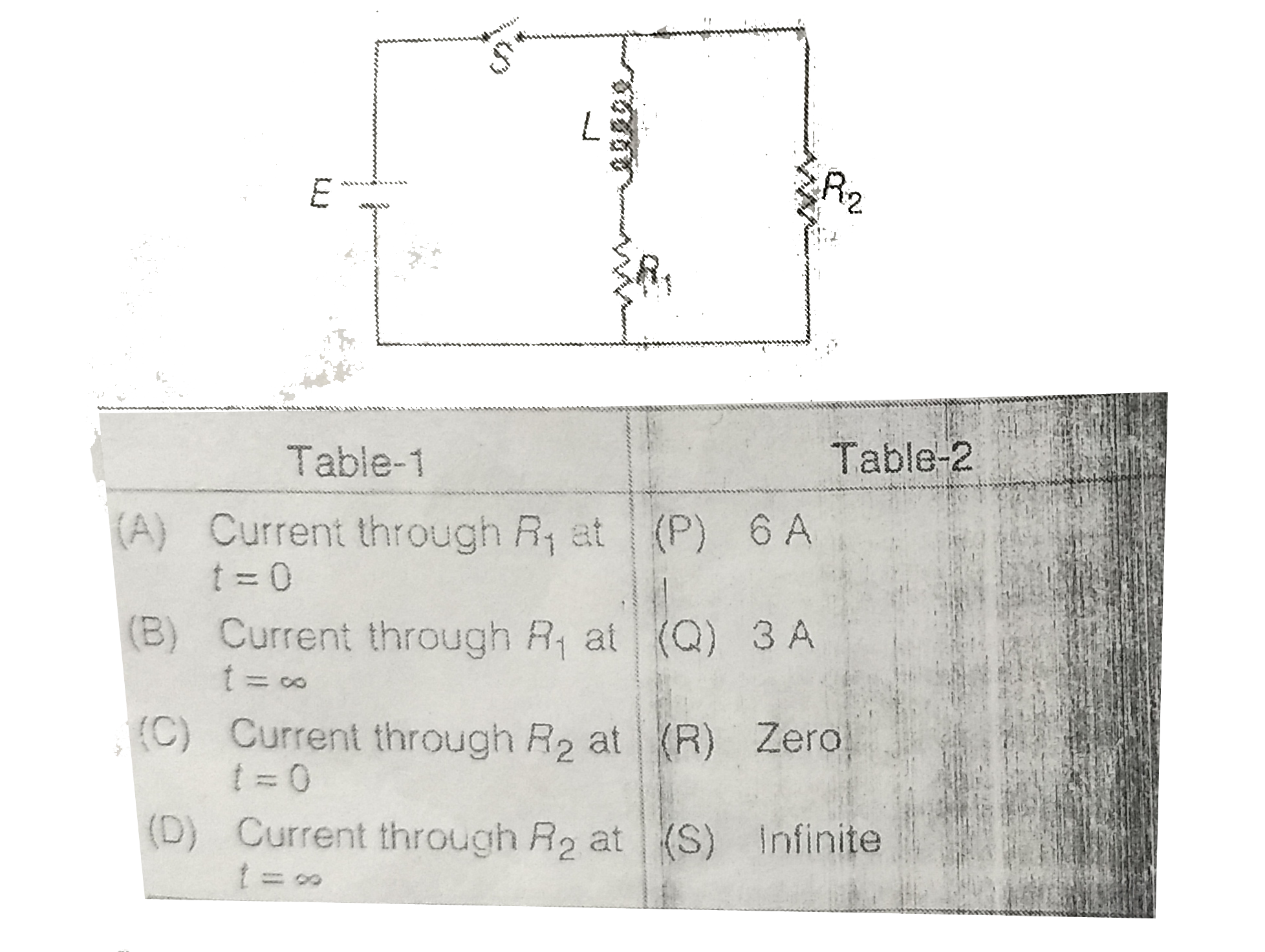
- In the circuit diagram shown in Figure E=18V , L=2H, R(1)=3Omega , R(2...
Text Solution
|
- In the circuit shown in figure L=10H, R=5Omega, E=15V. The switch S is...
Text Solution
|
- The figure below shown a battery with emf 15 V in a circuit with R(1) ...
Text Solution
|
- In the circuit as shown in figure the switch is closed at t = 0 . At t...
Text Solution
|
- Consider the circuit shown in the figure. If E=20V , R(1)=4Omega , R(2...
Text Solution
|
- In the circuit shown in figure , R(1)=R(2)=R(3)=R. Match the following
Text Solution
|
- In the circuit diagram shown in figure match the following two columns...
Text Solution
|
- In the circuit shown in figure switch S is closed at time t=0 Po...
Text Solution
|
- In the circuit diagram shown in Figure E=18V , L=2H, R(1)=3Omega , R(2...
Text Solution
|