A
B
C
D
Text Solution
Verified by Experts


Similar Questions
Explore conceptually related problems
Recommended Questions
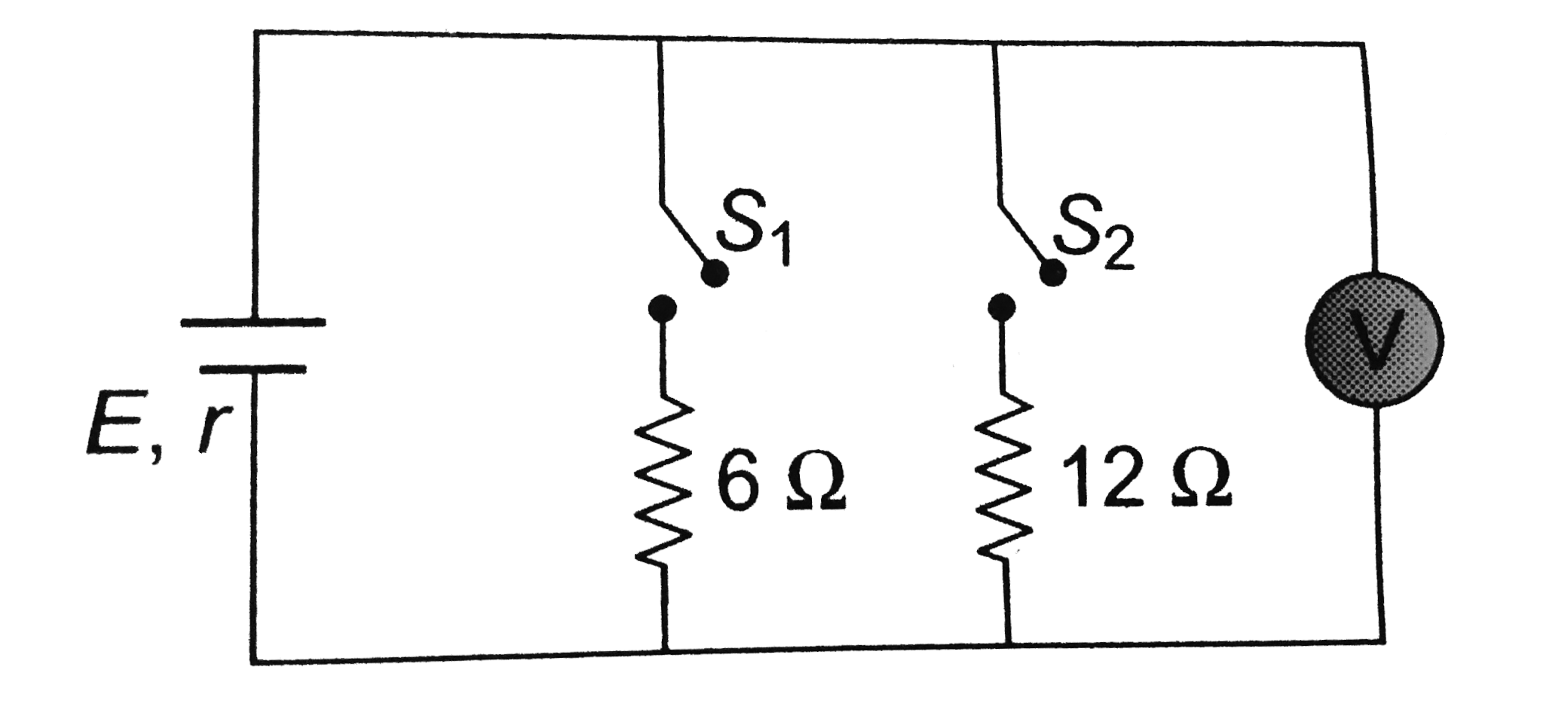
- In the circuit shown, when switch S(1) is closed and S(2) is open, the...
Text Solution
|
- In the circuits shows in S(1) and S(2) are switches. S(2) remains clos...
Text Solution
|
- In the circuit shows (Fig.) switches S(1) and S(3) have been closed fo...
Text Solution
|
- In the circuit shown, when switch S(1) is closed and S(2) is open, the...
Text Solution
|
- In the given ciruit Ammeter reading is same when both switches S(1),S(...
Text Solution
|
- In the circuit shown, the capacitor is initially charged with a 12V ba...
Text Solution
|
- In the circuit shown, the capacitor initially charged with a 12V batte...
Text Solution
|
- As shown in diagram initial charge on capacitor is zreo . Now switch S...
Text Solution
|
- In the circuit shown in figure reading of voltmeter is V(1) when onl...
Text Solution
|