A
B
C
D
Text Solution
Verified by Experts


Recommended Questions
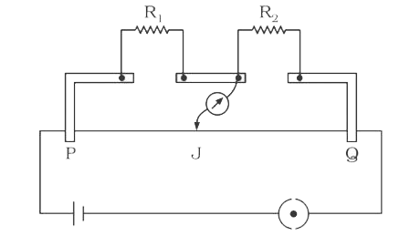
- The circuit diagram given in the figure shown the experimental setup f...
Text Solution
|
- An unknown resistance X is to be determined using resistances R1, R2 o...
Text Solution
|
- In the figure shown for given values of R1 and R2 the balance point fo...
Text Solution
|
- An unknown resistance 'X' is placed in the left gap and and a known re...
Text Solution
|
- In a metre bridge experiment, unknown resistance X and known resistan...
Text Solution
|
- The distance between the positions of two null points obtained in a me...
Text Solution
|
- A metal wire of circular cross section has a resistance R1 .The wire i...
Text Solution
|
- With two resistance R1 and R2 (>R1) in the two gaps of a metre bridge ...
Text Solution
|
- The circuit diagram given in the figure shown the experimental setup f...
Text Solution
|