Home
Class 12
PHYSICS
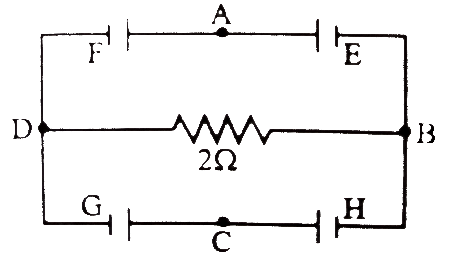
In the circuit shown E, F, G and H are c...

In the circuit shown `E, F, G` and `H` are cells of emf `2V, 1V, 3V` and `1V` respectively and their internal resistance are `2Omega, 1Omega, 3Omega` and `1Omega` respectively.

Text Solution

Verified by Experts

(i) `2/13 V, (ii) V_G=21/13V, V_H=9/13V`
Applying kirchoff's second law in loop BADB, `2-2j_1-j_1-1-2(j_1-j_2)=0`
Similarly applying kirchoff's second law in loop BDCB
`2(j_1-j_2)+3-3j_2-j_2-1=0`………(ii)
Solving Eqs. (i) and (ii) we get
`j_1=5/13,j_2=6/13 and j_1-j_2=-1/13`
(i) Potential difference between B and D,
`V_B+2(j_1-j_2)=V_D`
`therefore V_B-V_D=-2(j_1-j_2)=2/13 V`
(ii) `V_G=E_G-j_2r_G=3-6/13 times 3=21/13 V, V_H=E_H+j_2r_h=1+6/13 times 1=19/13V`
Promotional Banner

Similar Questions

Explore conceptually related problems

In the circuit shown in figure-3.159 cells E,F,G and H are of EMF 2V, 1V,3V and 1V respevitly and their internal resitance are 2Omega,1Omega,3Omega and 1Omega respectively Calculate (a) The potential difference between points B and D (d) The potential difference across the terminals of the cell G and H.

In the circuit shown in E, F, G, and H are cells of emf 2,1,3 and 1 V, respectively. The resistances 2Omega, 1Omega, 3Omega and 1Omega are their respectivle internal resistances. i. Find the potential difference between B and D. (ii) Calculate the potential differences across the terminals of each of the cells G and H.

In the circuit shown in figure E,F, G and H are cell of emf 2,1,3, and 1 V respectively. The resistances 2,1,3 and 1(Omega)are their respective internal resistance .Calculate (a)the potential difference between B and D and (b) the potential differences across the terminals of each of each of the cells G and H.

In the circuit shown in figure. The cells E,F,G and H have e.m.f's 2,1,3 and 1 V and internal resistance 2,1,3 and 1Omega respectively. Find the potential differences between points B and D, and across the terminals of the cells G and H.

Three cells of emf 2.0 v, 1.8 V and 1.5 V are connected in series. Their internal resistances are 0.05 Omega, 0.7 Omega " and " 1 Omega respectively. If the battery is connected to an external resistor of 4 Omega via a very resistance ammeter, what would be the reading in the ammeter ?

In the circuit shown in fig. the cell has emf 10V and internal resistance 1 Omega

A circuit consists of three bateries of emf E_(1) = 1V, E_(2)=2V and E_(3)=3V and internal resistance 1Omega, 2Omega and 1Omega respectively which are connected in parallel as shown in figure. The potential difference between points P and Q is