Text Solution
Verified by Experts
The correct Answer is:


Similar Questions
Explore conceptually related problems
NCERT EXEMPLAR-ALTERNATING CURRENT-Alternating Current
- When an AC voltage of 220 V is applied to the capacitor C
Text Solution
|
- The line the draws power supply to your house from street has
Text Solution
|
- If a LC circuit is considered analogous to a harmonically oscillating ...
Text Solution
|
- Draw the effective equivalent circuit of the circuit show in Fig. at v...
Text Solution
|
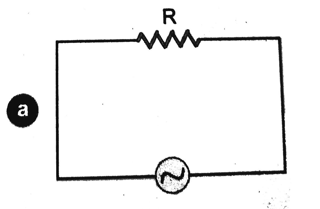
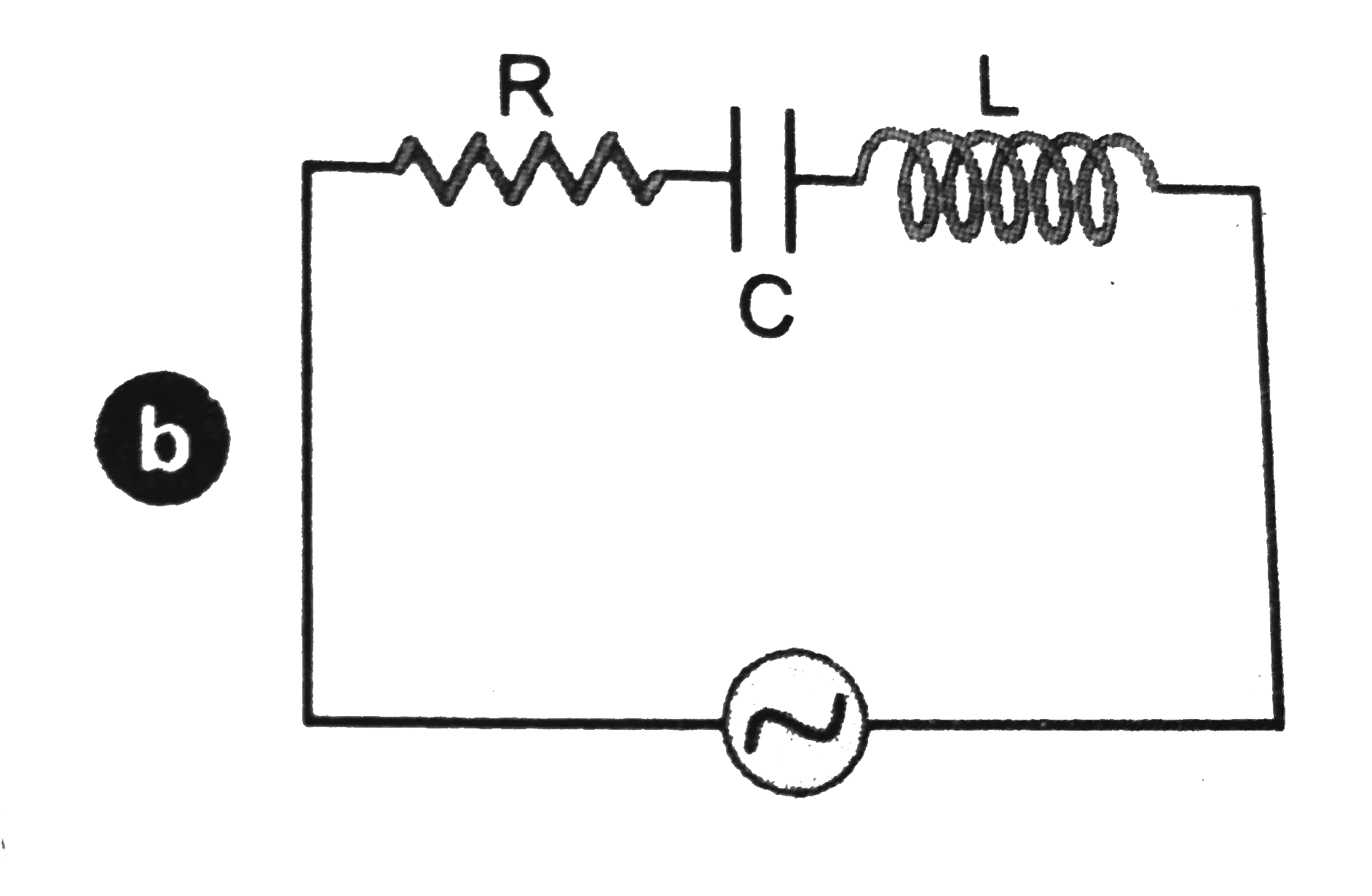
- Study the circuit (a) and (b) shown in Fig. and answer the following q...
Text Solution
|
- Can the instantaneous power output of an ac source ever be negative ? ...
Text Solution
|
- In series LCR circuit, the plot of I("max") versus omega is shown in f...
Text Solution
|
- The alternating current in a circuit is described by the graph shown i...
Text Solution
|
- How does the sign of the phase angle phi, by which the supply voltage ...
Text Solution
|
- A device 'X' is connected to an AC source. The variation of voltage, c...
Text Solution
|
- Both alternating current and direct are measured in amperes. But how i...
Text Solution
|
- A coil of 0.01 henry inductance and 1 ohm resistance is connected to 2...
Text Solution
|
- A 60 W load is connected to the secondary of a transformer whose prima...
Text Solution
|
- Explain why the reactance provided by a capacitor to an alternating cu...
Text Solution
|
- Explain why the reactance offered by an inductor increases with increa...
Text Solution
|
- An electrical device draws 2 kW power form AC mains [voltage 223 V (rm...
Text Solution
|
- 1 MW power is to be delivered from a power station to a town 10 km awa...
Text Solution
|
- Consider the L-C-R circuit shown in the fiure. Find the net current I ...
Text Solution
|
- For an LCR circuit driven at frequency omega, the equation reads L (di...
Text Solution
|
- In the LCR circuit shown in Fig., the ac driving voltage is upsilon = ...
Text Solution
|