


Similar Questions
Explore conceptually related problems
Recommended Questions
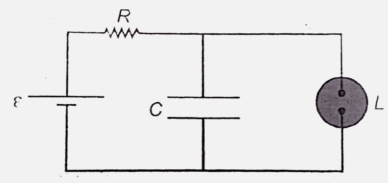
- Figure shows the circuit of a flashing lamp, used at construction site...
Text Solution
|
- The voltage across a lamp is (6.0 +- 0.1) V and the current passing th...
Text Solution
|
- In the circuit shown in Fig.a voltage V is connected across lamp L. Wh...
Text Solution
|
- Assertion (A) : A lamp is connected in series with a capacitor and ac ...
Text Solution
|
- An electronic flash lamp has 10 capacitors, each 10 muF, connected in ...
Text Solution
|
- Explain how the discharge phenomenon is applied in fluorescent lamps a...
Text Solution
|
- A 100muF capacitor is to have an energy content of 50J in order to ope...
Text Solution
|
- प्रश्नो के उत्तर दीजिए एक लैम्प से श्रेणीक्रम से जुडी चोक को एक dc ल...
Text Solution
|
- In an electric circuit, potential difference across a lamp is 20 V and...
Text Solution
|