Home
Class 12
PHYSICS
In the inductive circuit given in the fi...

In the inductive circuit given in the figure, the current rises after the switch is closed. At instant when the current is 15 mA, then potential difference across the inductor will be-

A

zero

B

240 V

C

180 V

D

60 V

Text Solution

Verified by Experts

The correct Answer is:
C

At any instant
`V_(R) + V_(L) = 240`
`iR + V_(L) = 240`
`V_(L) = 240 - iR`
`= 240-15 xx 10^(-3) xx 400 = 180 V`
Promotional Banner

Topper's Solved these Questions

Similar Questions

Explore conceptually related problems

In the circuit shown, rms circuit is 11 A . The potential difference across the inductor is

In the given circuit, with steady current, the potential difference across the capacitor is

In which of the following circuits is the current maximum just after the switch S is closed?

In the circuit shown if current for the diode is 20 muA , the potential difference across the diode is

In the circuit diagram the current through the battery immediately after the switch S is closed is

A resistor, capacitor, switch, and ideal battery are in series. Originally the capacitor is uncharged. The switch is then closed, allowing current of flow While the current is flowing, the potential difference across the resistor is

In the circuit as shown in figure the switch is closed at t = 0 . At the instant of closing the switch

A resistor, capacitor, switch, and ideal battery are in series. Originally the capacitor is uncharged. The switch is then closed, allowing current of flow While the current is flowing, the potential difference across the capacitor is

When the switch S is closed in the given circuit, the current passed through it is

CAREER POINT-UNIT TEST 8-Physics
  1. The real angle of dip, if a magnet is suspended at an angle of 30^(@) ...

    Text Solution

    |

  2. The relative permeability is represented by mu(r) and susceptibility i...

    Text Solution

    |

  3. In a uniform magneitc field of induced B a wire in the form of a semic...

    Text Solution

    |

  4. An alternating current I in an inductance coil varies with time t acco...

    Text Solution

    |

  5. The self inductance of a solenoid of length L, area of cross-section A...

    Text Solution

    |

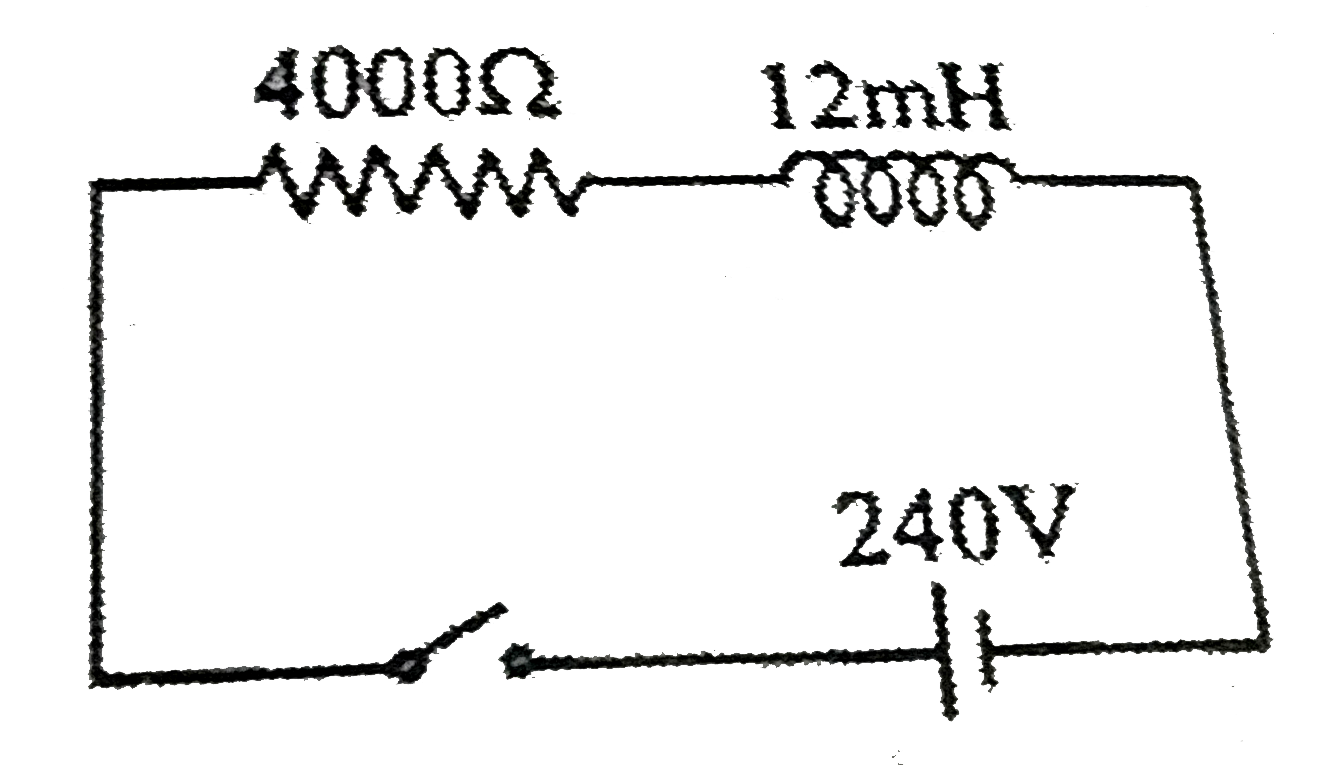
  6. In the inductive circuit given in the figure, the current rises after ...

    Text Solution

    |

  7. A current I = 10 sin (100pi t) amp. Is passed in first coil, which ind...

    Text Solution

    |

  8. The figure shows three circuits with identical batteries, inductors an...

    Text Solution

    |

  9. A small square loop of wire of side l is placed inside a large square ...

    Text Solution

    |

  10. In adjacent circuit, switch S is closed at t = 0. The time at which cu...

    Text Solution

    |

  11. A generator at a utility company produces 100 A of current at 4000 V. ...

    Text Solution

    |

  12. One 10V, 60W bulb is to be connected to 100V line. The required induct...

    Text Solution

    |

  13. An AC source of angular frequency omega is fed across a resistor R and...

    Text Solution

    |

  14. If the reading of the voltmeters vary with time as: V(1) = 20 sin omeg...

    Text Solution

    |

  15. The average and effective values for the waveshaphe shown in figure ar...

    Text Solution

    |

  16. An alternating current is given by (sqrt(3) sin omegat + cos omegat...

    Text Solution

    |

  17. The frequency of oscillation of current in the inductor is:

    Text Solution

    |

  18. A coil has an inductance of 0.7 H and is joined in series with a resis...

    Text Solution

    |

  19. Rms value of the saw-tooth voltage of peak value V(0) as shown in-

    Text Solution

    |

  20. A 2.5//pi muF capacitor and a 3000 ohm resistance are joined in series...

    Text Solution

    |