


Similar Questions
Explore conceptually related problems
Recommended Questions
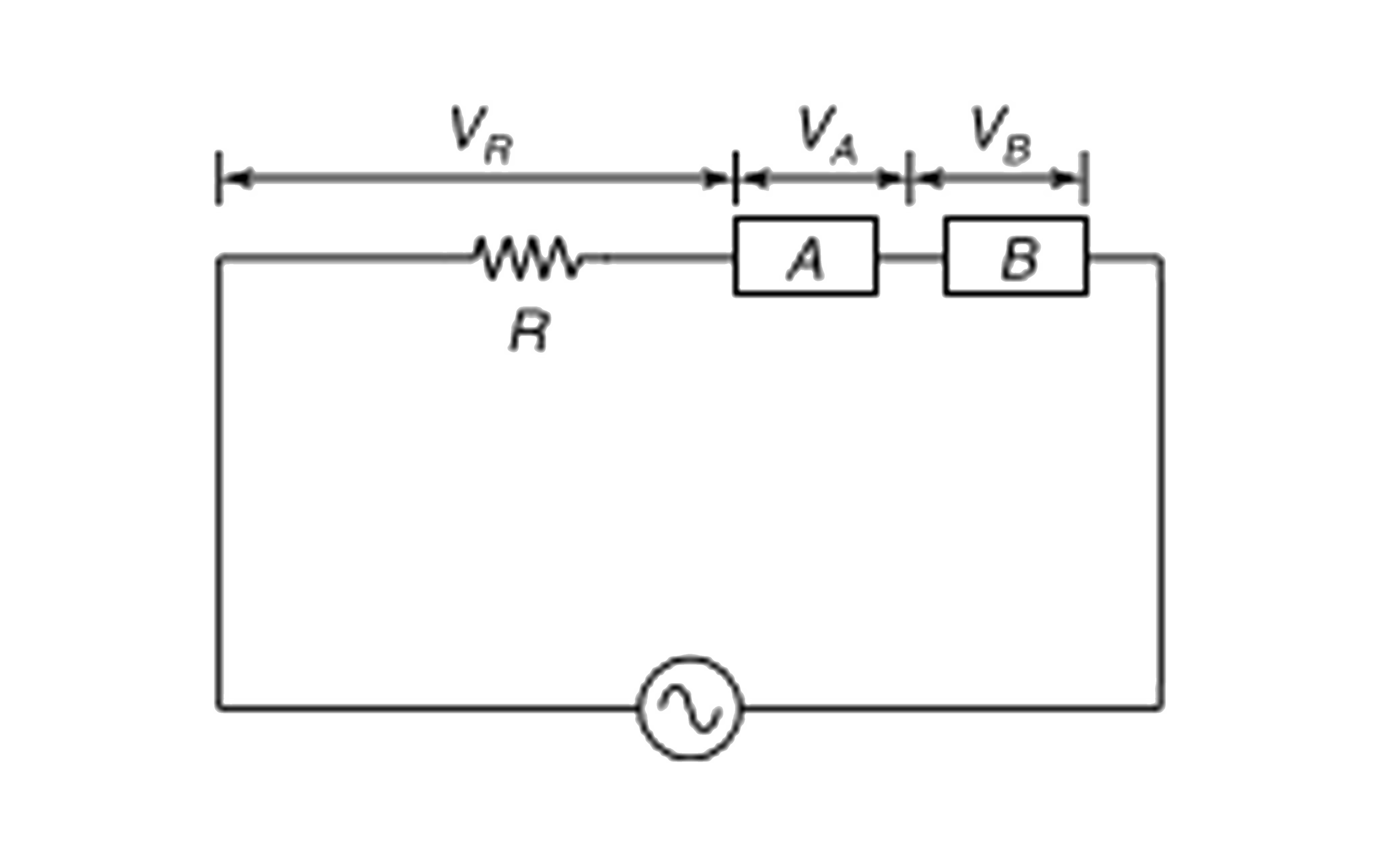
- In the circuit shown in the Figure, the voltage across resistance R, b...
Text Solution
|
- Voltage applied to an AC circuit and current flowing in it is given by...
Text Solution
|
- An alternating voltage V = V(0) sin omegat is applied across a circuit...
Text Solution
|
- In the circuit shown in the Figure, the voltage across resistance R, b...
Text Solution
|
- In the circuit shown the source voltage is given as v = V(0) sin omega...
Text Solution
|
- एक प्रत्यावर्ती धारा परिपथ में धारा i = i(0) sin (omegat-pi//2) प्रवा...
Text Solution
|
- In an AC circuit, voltage V = V(0)sin omegat and inductor L is connect...
Text Solution
|
- The values of current and voltage in an AC circuits are respectively I...
Text Solution
|
- In an L-C-R circuit, if V is the effective value of the applied voltag...
Text Solution
|