Text Solution
Verified by Experts
The correct Answer is:
Topper's Solved these Questions
Similar Questions
Explore conceptually related problems
NTA MOCK TESTS-NTA JEE MOCK TEST 28-PHYSICS
- A solenoid of inductance L and resistance R has a soft iron core . It ...
Text Solution
|
- In the figure shown , after the switch 's' is turned from postion ...
Text Solution
|
- A glass hemisphere (mu=1.5) has a radius of curvature of 16 cm. A smal...
Text Solution
|
- One mole of diatomic gas undergoes a process P=(P0)/([1+(V//V0)^3]) , ...
Text Solution
|
- A finite carrying - current wire is placed in a plane along with very ...
Text Solution
|
- Three blocks of A, B and C of equal mass m are placed one over the oth...
Text Solution
|
- Electromagnetic wave travel in medium at a speed of 2.0xx10^8ms^-1. Th...
Text Solution
|
- The height of a mercury barometer is 75 cm at sea level and 50 cm at t...
Text Solution
|
- A heavy plank of mass 100 kg hangs on three vertical wires of equal le...
Text Solution
|
- The fraction of atoms of radioactive element that decays in 6 days is ...
Text Solution
|
- As shown in the figure, a bob of mass m is tied by a massless string w...
Text Solution
|
- Consider telecommunication through optical fibres. Which of the follow...
Text Solution
|
- What is the conductivity of a semiconductor sample having electron con...
Text Solution
|
- Temperature of an ideal gas is 300 K . The final temperature of the ga...
Text Solution
|
- Radio waves coming at anglealpha to vetical are received by a radar af...
Text Solution
|
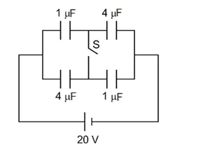
- For the circuit shown in the figure , the charge flown through the swi...
Text Solution
|
- A heavy nuleus having mass number 200 gets disintegrated into two smal...
Text Solution
|
- A horizontal rod of mass m=(3k)/(pi^2) kg and length L is pivoted at o...
Text Solution
|
- In a car race sound signals emitted by two cars are detected by the de...
Text Solution
|
- A small particle of mass m and charge Q is dropped in uniform horizont...
Text Solution
|
