Home
Class 12
PHYSICS
Let there be n resistors R(1) . . . R(...

Let there be n resistors `R_(1) . . . R_(n)` with `R_(max)=max(R_(1) . . . . R_(n))` and `R_("min")=min{R_(1) . . . R_(n)}`. Show that when they are connected in parallel the resultant resistance `R_(p)=R_("min")` and when they are connected in series, the resultant resistance `R_(S) gt R_(max)`. Interpret the result physically.

Text Solution

Verified by Experts

When all resistances are connected in parallel, the resultant resistance `R_(p)` is given by
`(1)/(R_(p))=(1)/(R_(1))+. . . . .+(1)/(R_(n))`
On multiplying both sides by `R_("min")` we have
`(R_("min"))/(R_(p))=(R_("min"))/(R_(1))+(R_("min"))/(R_(@))+. . . .+(R_("min"))/(R_(n))`
Here, in RHSlt there exist one term `(R_("min"))/(R_("min"))=1` and other terms are positive, so we have
`(R_("min"))/(R_(p))=(R_("min"))/(R_(1))+(R_("min"))/(R_(2))+ . . . .+(R_("min"))/(R_(n)) gt 1`
This shows that the resultant resistance `R_(p) lt R_("min")`
thus, in parallel combination, the equivalent resistance of resistors is less than the minimum resistance available in combination of resistors. Now, in series combination, the equivalent resistance is given by
`R_(S)=R_(1)+ . . . +R_(n)`
Here, in RHS, there exist one term having resistance `R_(max)`
So, we have
or `R_(S)=R_(1)+ . . .+R_(max)+ . . .+. . .+R_(n)`
`R_(S)=R_(1)+. . .+R_(max). . .+R_(n)=R_(max)+ . . .(R_(1)+. . .+)R_(n)`
or `R_(S)geR_(max)`
or `R_(S)=R_(max)(R_(1)+. . . +R_(n))`
Thus, in series combination, the equivalent resistance of resistors of resistors is greater than the maximum resistance available in combination resistors. Physical interpretation.
In Fig (b), `R_("min")` provides an equivalent route as in Fig. (a) for current. But in addition there are (n-1) routes by the remaining (n-1) resistors. Current in fig. (b) is greater than current in Fig. (a). Effective resistance in Fig (b) `lt R_("min")` Second circuit evidently affords a greater resistance.
In figure. (d), `R_(max)` provides an equivalent route as in fig. (c) for current. Current in figure. `(d) lt ` current in figure (c) Effective resistance in fig. (b) `lt R_(max)` second circuit evidently affords a greater resistance.

.
Promotional Banner

Topper's Solved these Questions

  • COMMUNICATION SYSTEM

    NCERT EXEMPLAR|Exercise Communication System|30 Videos
  • DUAL NATURE OF RADIATION AND MATTER

    NCERT EXEMPLAR|Exercise Dual Nature Of Radiation And Matter|29 Videos

Similar Questions

Explore conceptually related problems

If resistors of resistance R_(1) and R_(2) are connected in parallel,then resultant resistance is "

The resultant resistance of n wires each of resistance r ohms is R, when they are connected in parallel. When these n resistances are connected in series, the resultant resistance will be

The resultant resistance of n wires each of resistance r ohms is R ,when they are connected in parallel.When these n resistances are connected in series,the resultant resistance will be

The resistors of resistances R_(1)=100pm3" ohm and R"_(2)=200pm 4ohm are connected in series. The equivalent resistance of the series combination is

Two resistors of resistance R_1 and R_2 having R_1>R_2 are connected in parallel. For equivalent resistance R, the correct statement is

There are n similar conductors each of resistance R . The resultant resistance comes out to be x when connected in parallel. If they are connected in series, the resistance comes out to be

Two resistors of resistances R_(1)=(300+-3) Omega and R_(2)=(500+-4) Omega are connected in series. The equivalent resistance of the series combination is

Two resistors of resistance R_(1) and R_(2) having R_(1) gt R_(2) are connected in parallel. For equivalent resistance R, the correct statement is

The resultant resistance value of n resistance each of r ohms and connected is series is X. When those n , resistance are connected in parallel , the resultant values is .

When two resistors of resistances R_1 and R_2 are connected in parallel, the net resistance is 3 Omega . When connected in series, its value is 16 Omega . Calculate the values of R_1 and R_2 .

NCERT EXEMPLAR-CURRENT ELECTRICITY-Current Electricity
  1. Is the motion of a charge across junction momentum conserving ? Why or...

    Text Solution

    |

  2. The relaxation time tau is nearly independent of applied electric fiel...

    Text Solution

    |

  3. What are the advantages of the nll-point method in a Wheatstone bridge...

    Text Solution

    |

  4. What is the advantages of using thick metallic strips to join wires in...

    Text Solution

    |

  5. For wiring in the home, one uses Cu wires or A1 wires. What considerat...

    Text Solution

    |

  6. Why are alloys used for making standard resistance coils?

    Text Solution

    |

  7. Power P is to be delivered to a device via transmission cables having ...

    Text Solution

    |

  8. AB is a potentiometer wire Fig. If the value of R is increased, in whi...

    Text Solution

    |

  9. While doing an experiment with potentiometer (figure) it was found tha...

    Text Solution

    |

  10. A cell of emf E and internal resistance r is connected across an exter...

    Text Solution

    |

  11. First a set of n equal resistors of R each are connected in series to ...

    Text Solution

    |

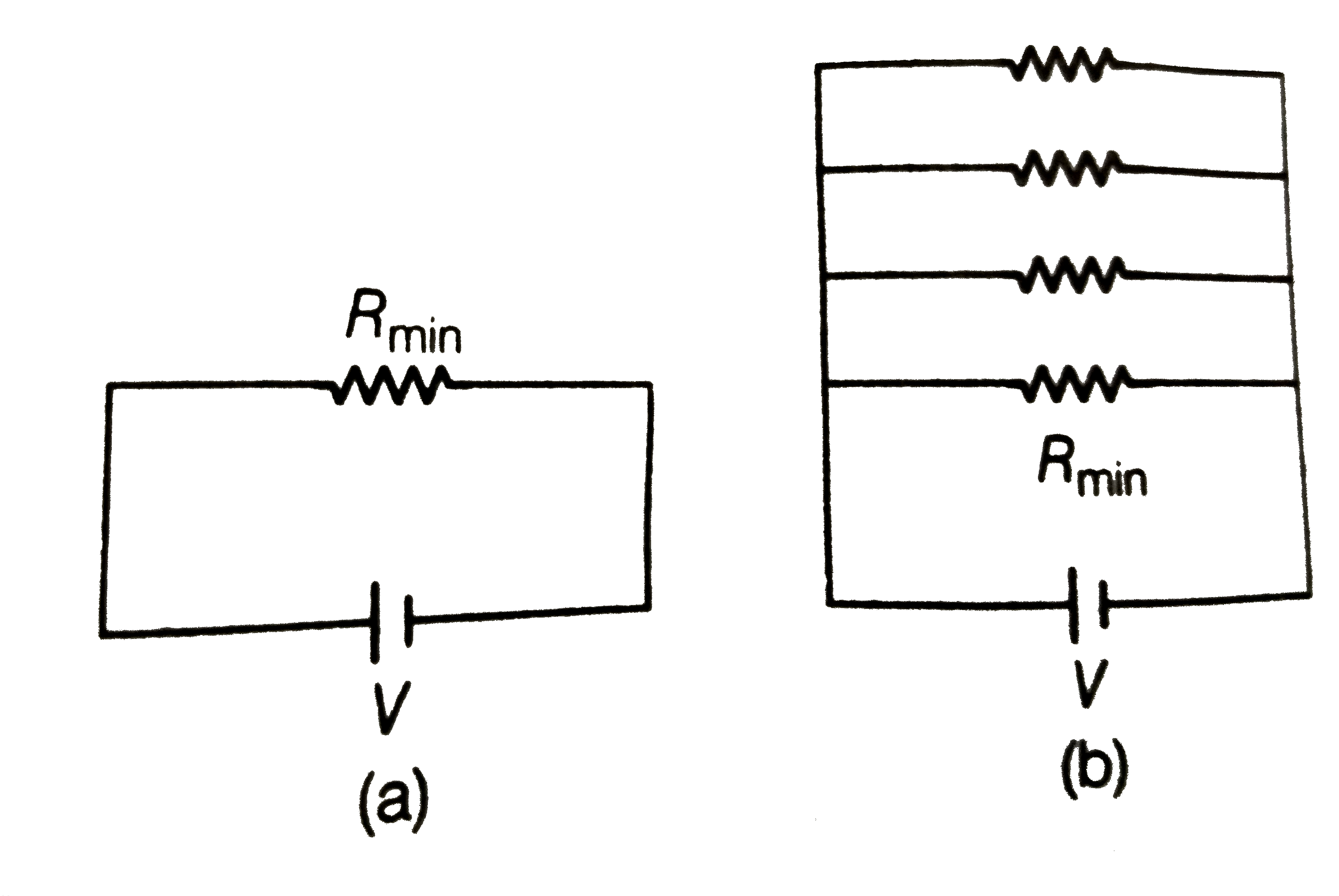
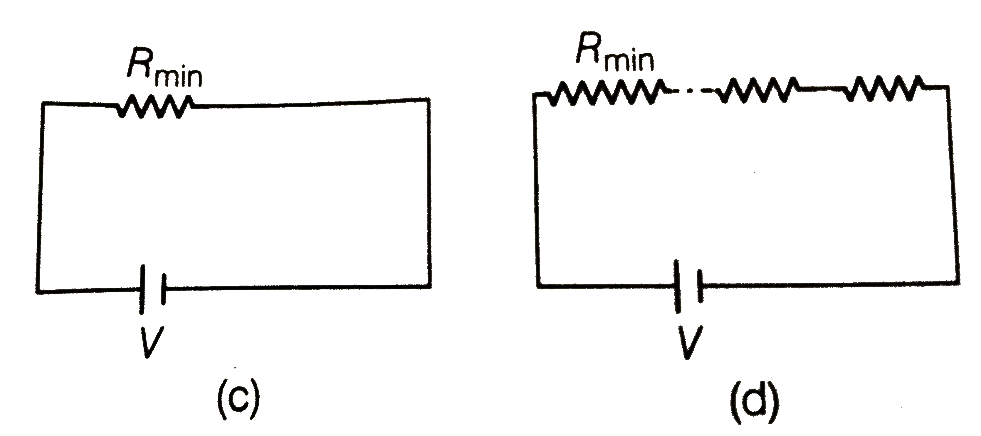
  12. Let there be n resistors R(1) . . . R(n) with R(max)=max(R(1) . . ....

    Text Solution

    |

  13. The circuit in Fig. shows two cells connected in opposition to each o...

    Text Solution

    |

  14. Two cells of same emf E but internal resistance r(1) and r(2) are conn...

    Text Solution

    |

  15. Two conductors are made of the same material and have the same length....

    Text Solution

    |

  16. Suppose there is a circuit consister of only resistance and batteries ...

    Text Solution

    |

  17. Two cells of voltage 10Vand 2 V and internal resistance 10 Omega and 5...

    Text Solution

    |

  18. A room AC run for 5 hour at a voltage of 220V The wiring of the room c...

    Text Solution

    |

  19. In an experiment with a potentiometer, V(B)=10V. R is adjusted to the ...

    Text Solution

    |

  20. (a). Consider circuit in figure. How much energy is absorbed by electr...

    Text Solution

    |