Home
Class 12
PHYSICS
A 100 W bulb B(1) and two 60 W bulbs B(2...


A 100 W bulb `B_(1)` and two 60 W bulbs `B_(2)` and `B_(3)`, are connected to a 250V source, as shown in the figure now `W_(1),W_(2)` and `W_(3)` are the output powers of the bulbs `B_(1),B_(2)` and `B_(3)` respectively then

A

`W_(1) gt W_(2) = W_(3)`

B

`W_(1) gt W_(2) gt W_(3)`

C

`W_(1) lt W_(2) = W_(3)`

D

`W_(1) lt W_(2) lt W_(3)`

Text Solution

Verified by Experts

The correct Answer is:
D
Promotional Banner

Topper's Solved these Questions

  • PRACTICE PAPPER

    NCERT FINGERTIPS|Exercise Practice Paper 2|50 Videos
  • NUCLEI

    NCERT FINGERTIPS|Exercise Assertion And Reason|15 Videos
  • RAY OPTICS AND OPTICAL INSTRUMENTS

    NCERT FINGERTIPS|Exercise Assertion And Reason|15 Videos

Similar Questions

Explore conceptually related problems

A 100 W bulb B_1 , and two 60 W bulbs B_2 and B_3 are connected to a 250 V source as shown in the figure. Now W_1,W_2 and W_3 are the output powers of the bulbs B_1, B_2 and B_3 respectively. Then

A 100 W bulb B_1 , and two 60 W bulb B_2 and B_3 , are connected to a 250 V source, as shown in figure. Now W_1, W_2 and W_3 are the output powers of the bulbs B_1, B_2 and B_3 , respectively. Then

Three bulbs B_(1), B_(2) and B_(3) are connected to the mains as shown in Fig. 7.28 . How will the brightness of bulb B_(1) be affected B_(2) or B_(3) are disconnected from the circuit?

Three bulbs of 40 W , 60 W and 100 W are connected in series with a 240 V source.

Three identical bulbs B_(1),B_(2) and B_(3) are connected to the mains as shown in figure. If B_(3) is disconnected for the from the circuit by opening switch S, then incandescence of bulb B_(1) will . ,

When two electric bulbs of 40W and 60W are connected in parallel, then the:

Bulb B_1(100W - 250W) and bulb B_2(100W - 200V) are connected across 250V. What is potential drop across B_2 ?

Two electric bulbs , rated at (25W,220V) and (100W,220V), are connected in series across a 220 V voltage source , if the 25W and 100W bulbs draw powers P_(1) and P_(2) Respectively , then :

NCERT FINGERTIPS-PRACTICE PAPPER-Practice Paper 3
  1. A voltmeter having a resistance of 1800 Omega employed to measure the ...

    Text Solution

    |

  2. A microammeter has as resistance of 100 Omega and full scale range of ...

    Text Solution

    |

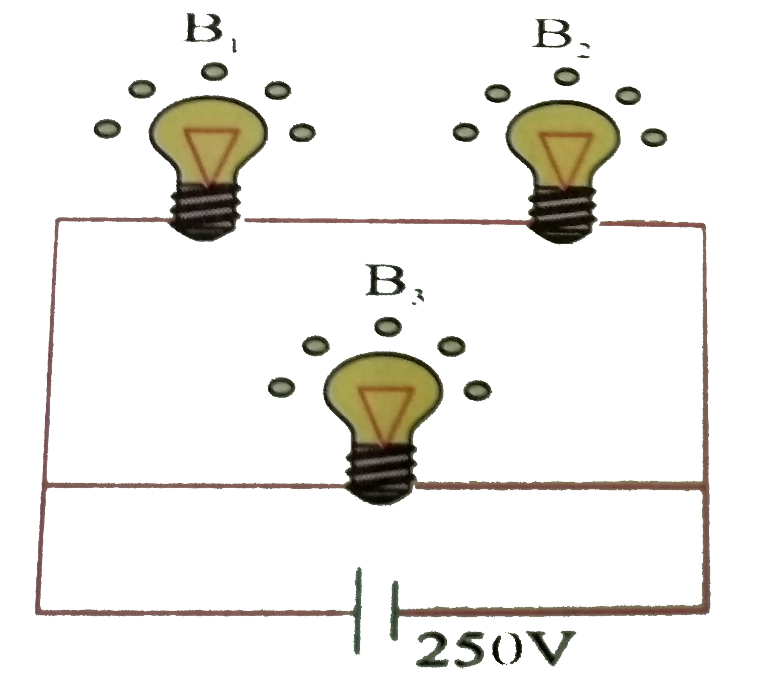
  3. A 100 W bulb B(1) and two 60 W bulbs B(2) and B(3), are connected to a...

    Text Solution

    |

  4. A short conducting rod P of length 3.0 cm is placed parallel to an nea...

    Text Solution

    |

  5. A rectangular loop carrying a current i is situated near a long strai...

    Text Solution

    |

  6. An electron and a proton enter a magnetic field at right angles to the...

    Text Solution

    |

  7. A gang capacitor is formed by interlocking a number of plates as shown...

    Text Solution

    |

  8. A galvanometer of resistance 25Omega is connected to a battery of 2 vo...

    Text Solution

    |

  9. A rectangular coil of 20 turns and area of cross-section 25 cm^(2) has...

    Text Solution

    |

  10. For perfectly coupled coils, the coupling coefficient should be equal ...

    Text Solution

    |

  11. A 200 muF capacitor in series with a 100 Omega resistance is connected...

    Text Solution

    |

  12. The efficiency of a transformer is 90%. The transformer is rated for o...

    Text Solution

    |

  13. In an experiment to find focal length of a concave mirror, a graph is ...

    Text Solution

    |

  14. In a reflecting astronomical telescope, if the objetcive (a spherical ...

    Text Solution

    |

  15. Which one of the following is a possible nuclear reaction ?

    Text Solution

    |

  16. A 5 W source emits monochromatic light of wavelength 5000 Å. When plac...

    Text Solution

    |

  17. Calculate in how many months , (3/4)^(th) of the substance will dacay,...

    Text Solution

    |

  18. Which of the following statements is not true?

    Text Solution

    |

  19. The transfer ration of a transistor is 50. The input resistance of th...

    Text Solution

    |

  20. Given below are four logic gates symbol (figure). Those for OR, NOR an...

    Text Solution

    |