Home
Class 12
PHYSICS
Which of the following figure correctly ...

Which of the following figure correctly depicts the Lenz’s law. The arrows show the movement of the labelled pole of a bar magnet into a closed circular loop and the arrows on the circle show the direction of the induced current

A

B

C

D

Text Solution

Verified by Experts

The correct Answer is:
A

When the north pole of a bar magnet moves towards the coil, the induced current in the coil flows in a direction such that the coil presents its north pole to the bar magnet as shown in Fig. (a).
Therefore, the induced current flows in the coil in the anti-clockwise direction. When the north pole of a bar magnet moves away from the coil, then the induced current in the coil flows in a direction such that the coil presents its south pole to the bar magnet as shown in Fig. (b).

Therefore, induced current flows in the coil in the clockwise direction.
Promotional Banner

Topper's Solved these Questions

  • ELECTROMAGNETIC INDUCTION

    DC PANDEY|Exercise Medical entrance special format questions|17 Videos
  • ELECTROMAGNETIC INDUCTION

    DC PANDEY|Exercise Match the columns|5 Videos
  • ELECTROMAGNETIC INDUCTION

    DC PANDEY|Exercise Check point|60 Videos
  • CURRENT ELECTRICITY

    DC PANDEY|Exercise Medical entrances gallery|97 Videos
  • ELECTROMAGNETIC WAVES

    DC PANDEY|Exercise Sec C|22 Videos

Similar Questions

Explore conceptually related problems

A bar magnet is moved in the direction indicated by the arrow between two coil PQ and CD . Predict the directions of induced current in each coil.

A bar magnet with its north (N) and south (S) poles as shown in the following figure is initially moving to the left, along the axis of, and away from a circular conducting loop. A current l is induced in the loop, with a being the acceleration of the magnet due to this current. As seen from the magnet looking in the direction of the loop,

A closed conducting ring is placed in between two bar magnets as shown in the figure. The pole strenght of M_(1) is double that of M_(2) . When the two bar magnets are at same distance from the centre of the ring, the bar magnet M_(1) has given a velocity 2v while M_(2) is given velocity v in the direction as shown in the figure. The direction of induced current in the ring as seen from X X from this moment to the moment till bar magnets collide is

A closed conducting ring is placed in between two bar magnets as shown in the figure. The pole strength of M_1 is double that of M_2 . When the two bar magnets are at same distance from the centre of the ring, the bar magnet M_1 has given a velocity 2v while M_2 is given velocity v in the direction as shown in the figure. The direction of induced current in the ring as seen from XX from this moment to the moment till bar magnets collide is

DC PANDEY-ELECTROMAGNETIC INDUCTION-Taking it together
  1. A uniform but time varying magnetic field is present in a circular reg...

    Text Solution

    |

  2. A conducting rod PQ of length L = 1.0 m is moving with a uniform speed...

    Text Solution

    |

  3. A conducting rod AC of length 4l is rotated about point O in a uniform...

    Text Solution

    |

  4. The current in an L-R circuit builds upto 3//4th of its steady state v...

    Text Solution

    |

  5. A rectangular coil ABCD which is rotated at a constant angular veolcit...

    Text Solution

    |

  6. A right angled triangle abc, made from a metallic wire, moves at a uni...

    Text Solution

    |

  7. In the circuit shown below, the key K is closed at t =0. The current t...

    Text Solution

    |

  8. The figure shows three circuit with identical batteries, inductors, an...

    Text Solution

    |

  9. The graph shows the variation in magnetic flux phi(t) with time throug...

    Text Solution

    |

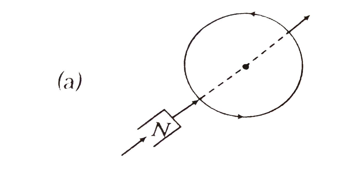
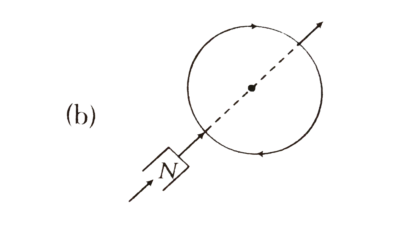
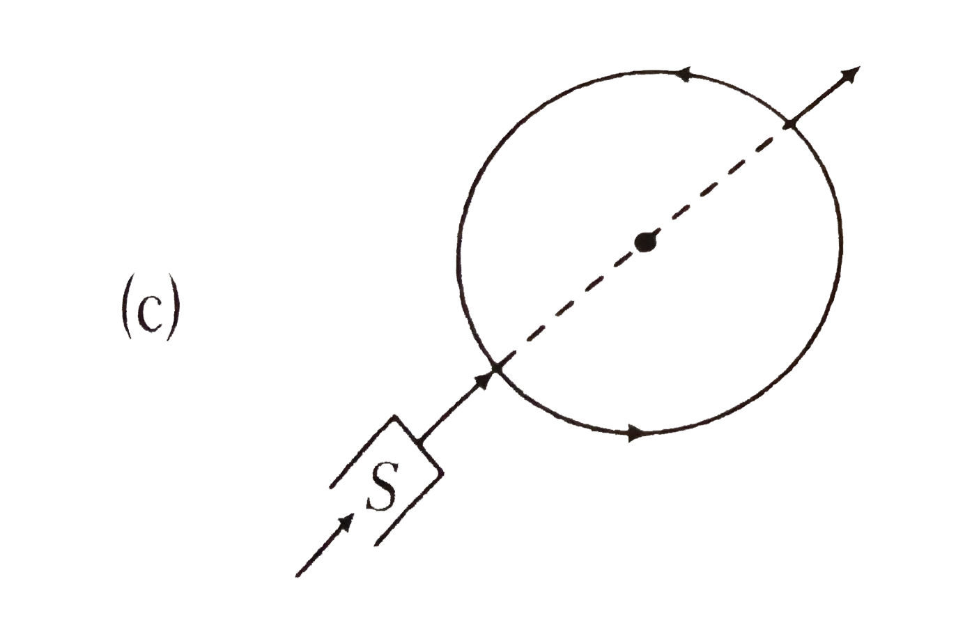
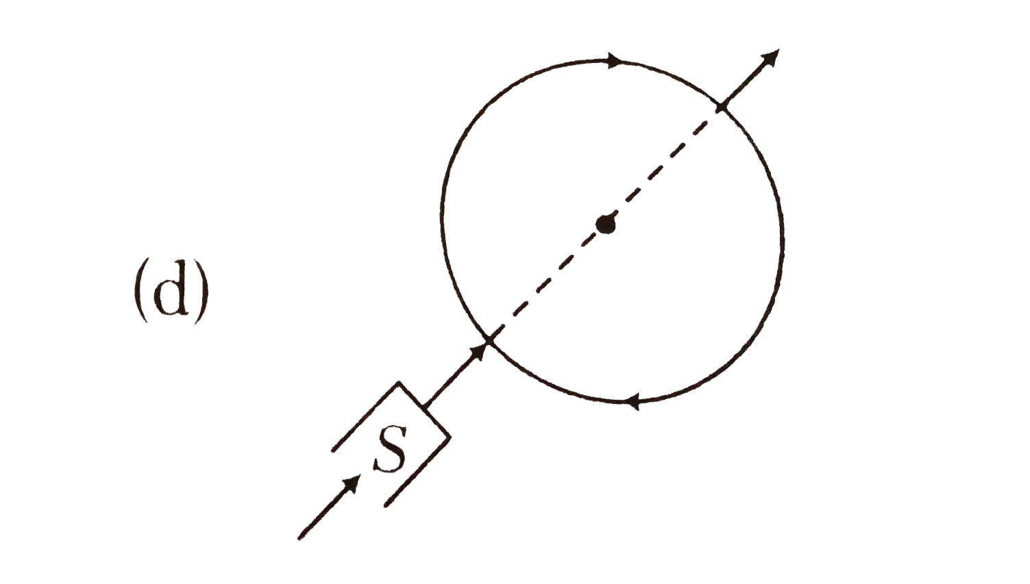
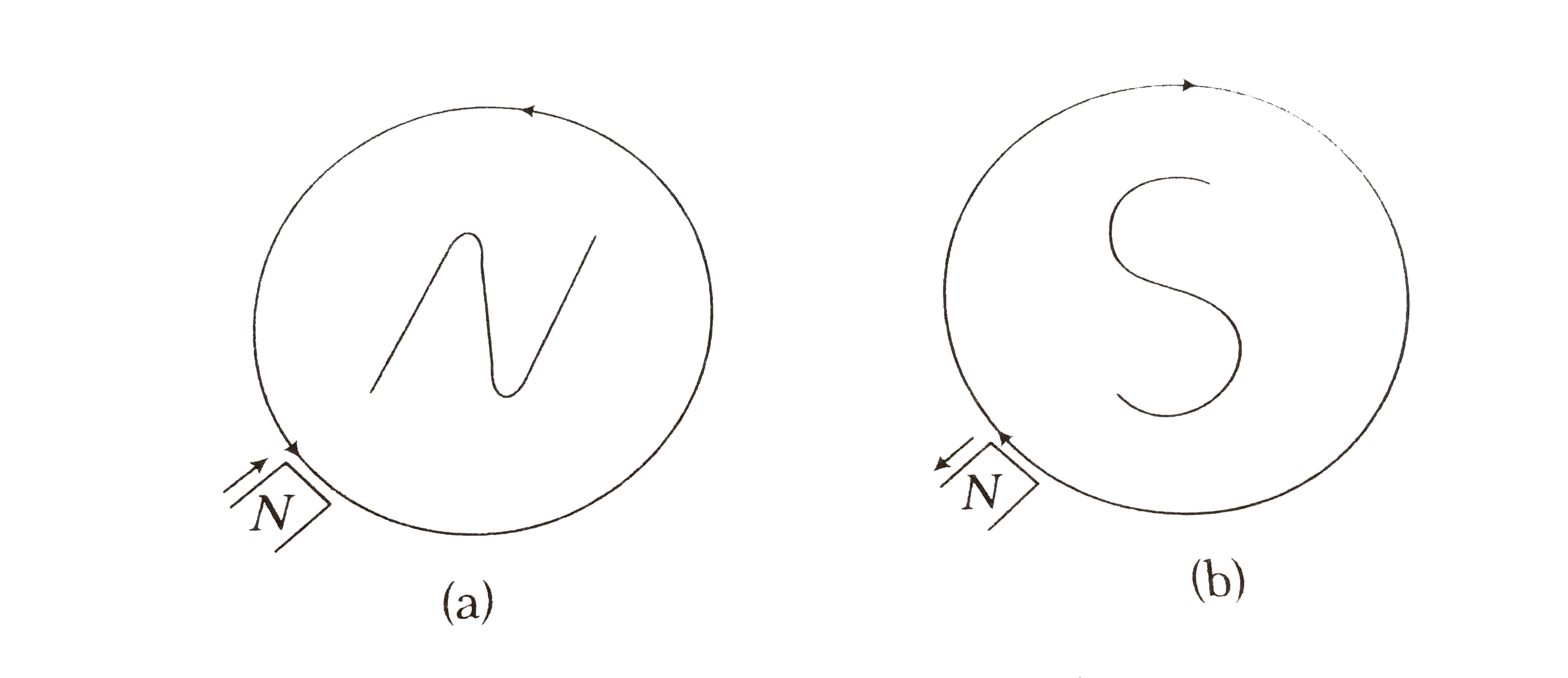
  10. Which of the following figure correctly depicts the Lenz’s law. The ar...

    Text Solution

    |

  11. A metalic ring is dropped down, keeping its plane perpendicular to a c...

    Text Solution

    |

  12. An inductor (L =0.03 H) and a resistor (R = 0.15k(Omega)) are connecte...

    Text Solution

    |

  13. An inductor of inductance L = 400 mH and resistors of resistance R(1) ...

    Text Solution

    |

  14. There are two solenoid of same length and inductance L but their diame...

    Text Solution

    |

  15. A rectangular loop of length 'l' and breadth 'b' is placed at a distan...

    Text Solution

    |

  16. A circular coil of one turn of radius 5.0cm is rotated about a diamete...

    Text Solution

    |

  17. A non-conducting ring having q uniformly distributed over its circumfe...

    Text Solution

    |

  18. A uniform but time-varying magnetic field B(t) exists in a circular re...

    Text Solution

    |

  19. As shown in the figure, P and Q are two coaxial conducting loops separ...

    Text Solution

    |

  20. A magnet is made to oscillate with a particular frequency, passimg thr...

    Text Solution

    |