A
B
C
D
Text Solution
Verified by Experts
The correct Answer is:


Similar Questions
Explore conceptually related problems
Recommended Questions
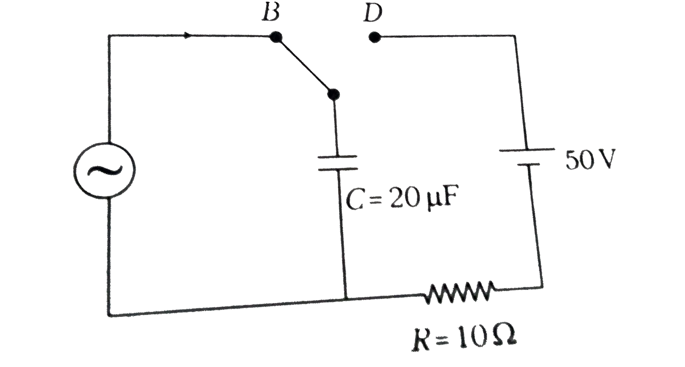
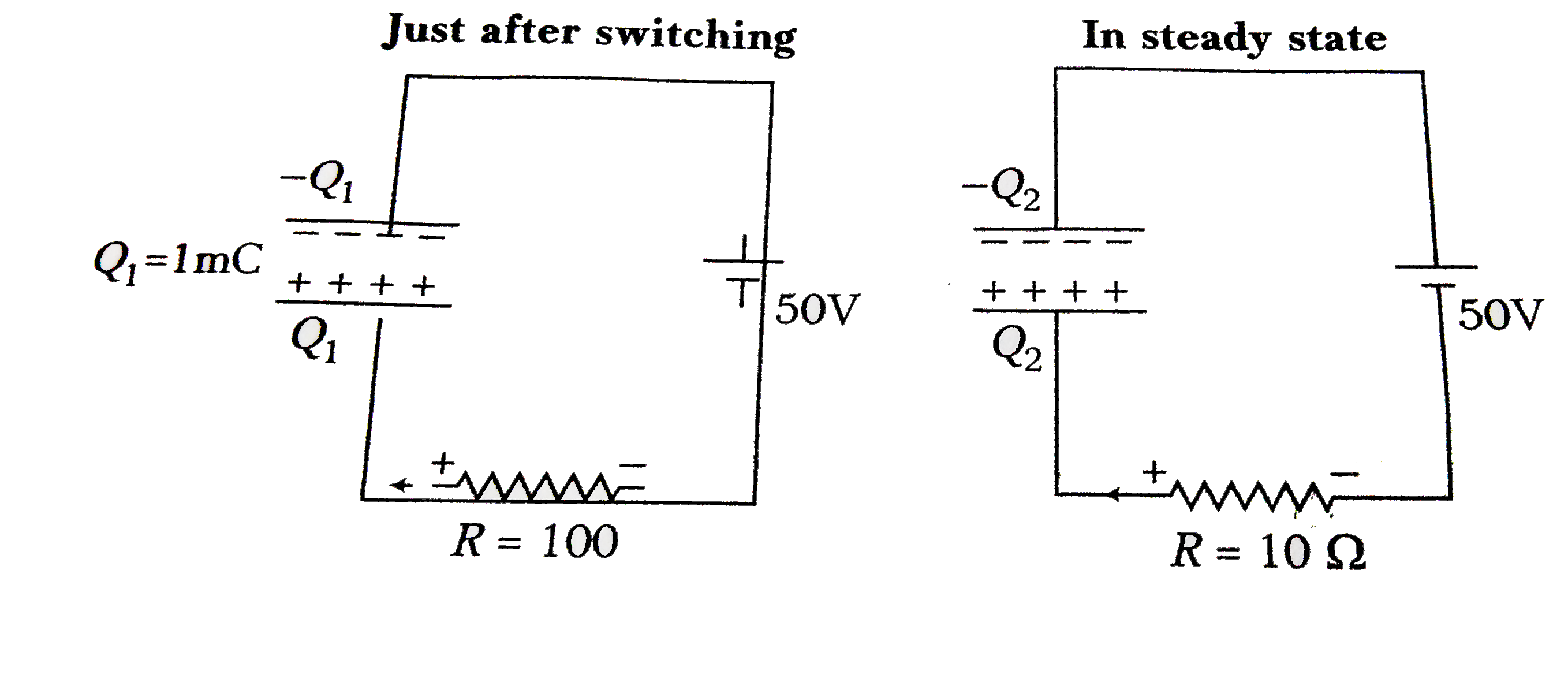
- At time t = 0 , terminal A in the circuit shown in the figure is conne...
Text Solution
|
- The switch S shown in figure is kept closed for a long time and is the...
Text Solution
|
- At time t = 0 , terminal A in the circuit shown in the figure is conne...
Text Solution
|
- In the circuit shown in figure switch S is closed at time t=0 Cu...
Text Solution
|
- Current and voltage in AC are I = underset(o)(I) sin (omegat + pi/4), ...
Text Solution
|
- If an alternating current is given by i = a sin (omegat) + b cos (omeg...
Text Solution
|
- At time t = 0, terminal A in the circuit shown in the figure is connec...
Text Solution
|
- चित्र में दर्शाए गए परिपथ में समय t = 0 पर बिंदु A को स्विच द्वारा बिं...
Text Solution
|
- चित्र में दर्शाए गए परिपथ में समय =0 पर बिन्दु A को स्विच द्वारा बिन्द...
Text Solution
|