Text Solution
Verified by Experts
The correct Answer is:


Topper's Solved these Questions
ELECTRICITY
LAKHMIR SINGH & MANJIT KAUR|Exercise Very Short Answer Type Questions|1 VideosELECTRICITY
LAKHMIR SINGH & MANJIT KAUR|Exercise Short Answer Type Questions|2 VideosELECTRICITY
LAKHMIR SINGH & MANJIT KAUR|Exercise Sample Problem|1 VideosMAGNETIC EFFECT OF ELECTRIC CURRENT
LAKHMIR SINGH & MANJIT KAUR|Exercise NCERT BOOK|2 Videos
Similar Questions
Explore conceptually related problems
LAKHMIR SINGH & MANJIT KAUR-ELECTRICITY -Exercise
- For the circuit shown in the diagram below: What is the value of:...
Text Solution
|
- The resistors, with resistances 5 Omega and 10 Omega respectively are ...
Text Solution
|
- The circuit diagram given below shows the combination of three resisto...
Text Solution
|
- In the circuit diagram given below, the current flowing across 5 ohm ...
Text Solution
|
- A resistor has a resistance of 176 ohms. How many of these resistors s...
Text Solution
|
- An electric heater which is connected to a 220V supply line has two re...
Text Solution
|
- In the circuit diagram given below five resistances of 10 Omega, 40 Om...
Text Solution
|
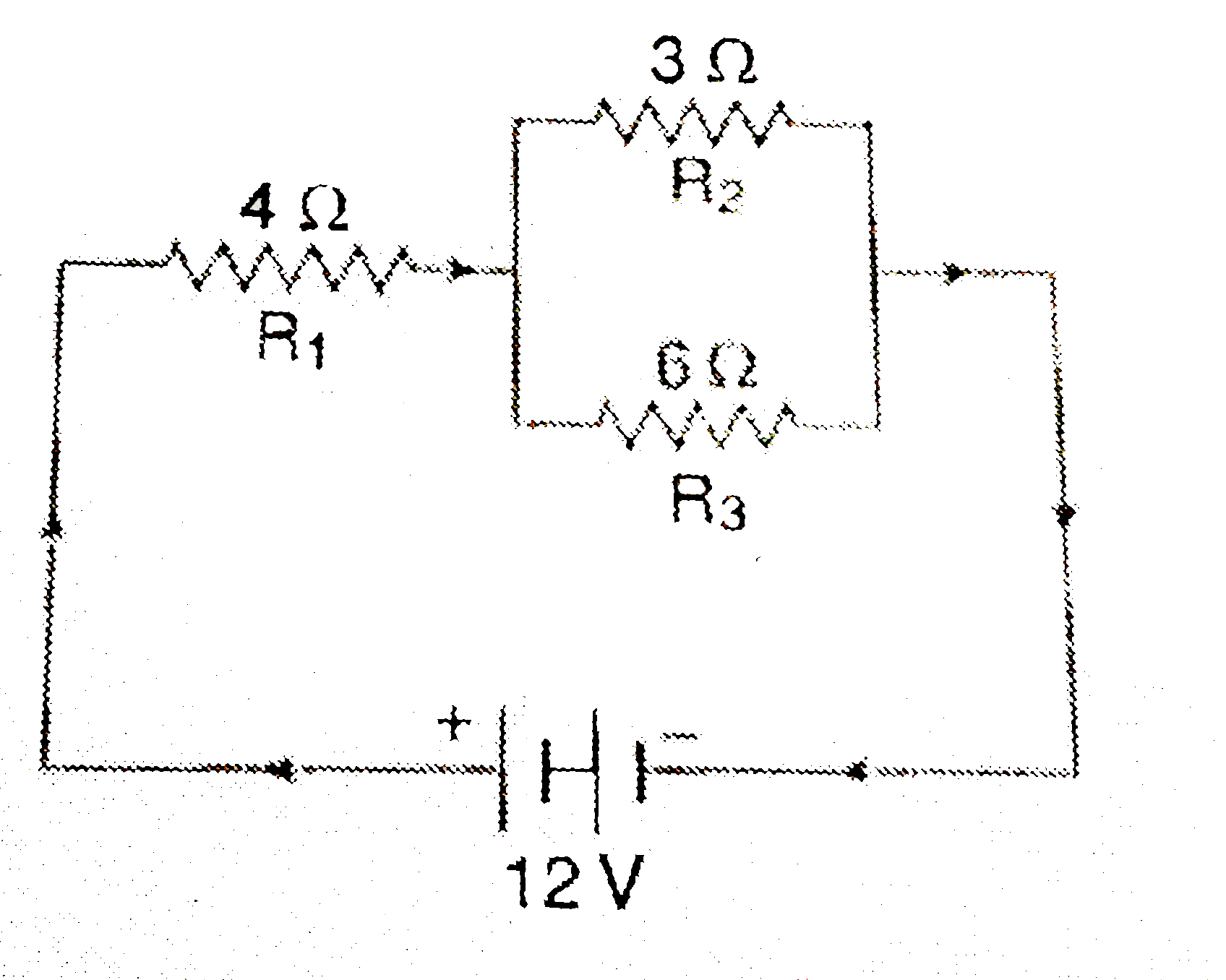
- In the circuit diagram given below, three resistors R(1),R(2), and R(3...
Text Solution
|
- A p.d. of 4V is applied to two resistors of 6 Omega and 2 Omega connec...
Text Solution
|
- A p.d. of 6V is applied to two resistors of 3 Omega and 6Omega connect...
Text Solution
|
- In the circuit shown below, the voltmeter reads 10V. (a) What is ...
Text Solution
|
- In the circuit given below: (a) What is the combined resistance...
Text Solution
|
- A 5V battery is connected to two 20 Omega resistors which are joined t...
Text Solution
|
- The figure given below shows an electric circuit in which current flow...
Text Solution
|
- A 4Omega coil and a 2Omega coil are connected in parallel. What is the...
Text Solution
|
- (a) With the help of a circuit diagram, deduce the equivalent resistan...
Text Solution
|
- (a) With the help of a diagram, derive the formula for the resultant r...
Text Solution
|
- (a) With the help of a circuit diagram, obtain the relation for the eq...
Text Solution
|
- (a) Explain with the help of a labelled circuit diagram, how you will ...
Text Solution
|
- The figure given below shows three resistors: Their combined resi...
Text Solution
|