A
B
C
D
Text Solution
Verified by Experts
The correct Answer is:


Topper's Solved these Questions
THE HUMAN EYE AND THE COLOURFUL WORLD
LAKHMIR SINGH & MANJIT KAUR|Exercise Long Answer Type Question|3 VideosTHE HUMAN EYE AND THE COLOURFUL WORLD
LAKHMIR SINGH & MANJIT KAUR|Exercise NCERT Book|14 VideosTHE HUMAN EYE AND THE COLOURFUL WORLD
LAKHMIR SINGH & MANJIT KAUR|Exercise Long Answer Type Questions|2 VideosTEST PAPER 4
LAKHMIR SINGH & MANJIT KAUR|Exercise SECTION A|10 Videos
Similar Questions
Explore conceptually related problems
LAKHMIR SINGH & MANJIT KAUR-THE HUMAN EYE AND THE COLOURFUL WORLD -Multiple Choice Questions
- The rest positions of the needles in a milliammeter and voltmeter not ...
Text Solution
|
- The current following through a resistor connected in an electric circ...
Text Solution
|
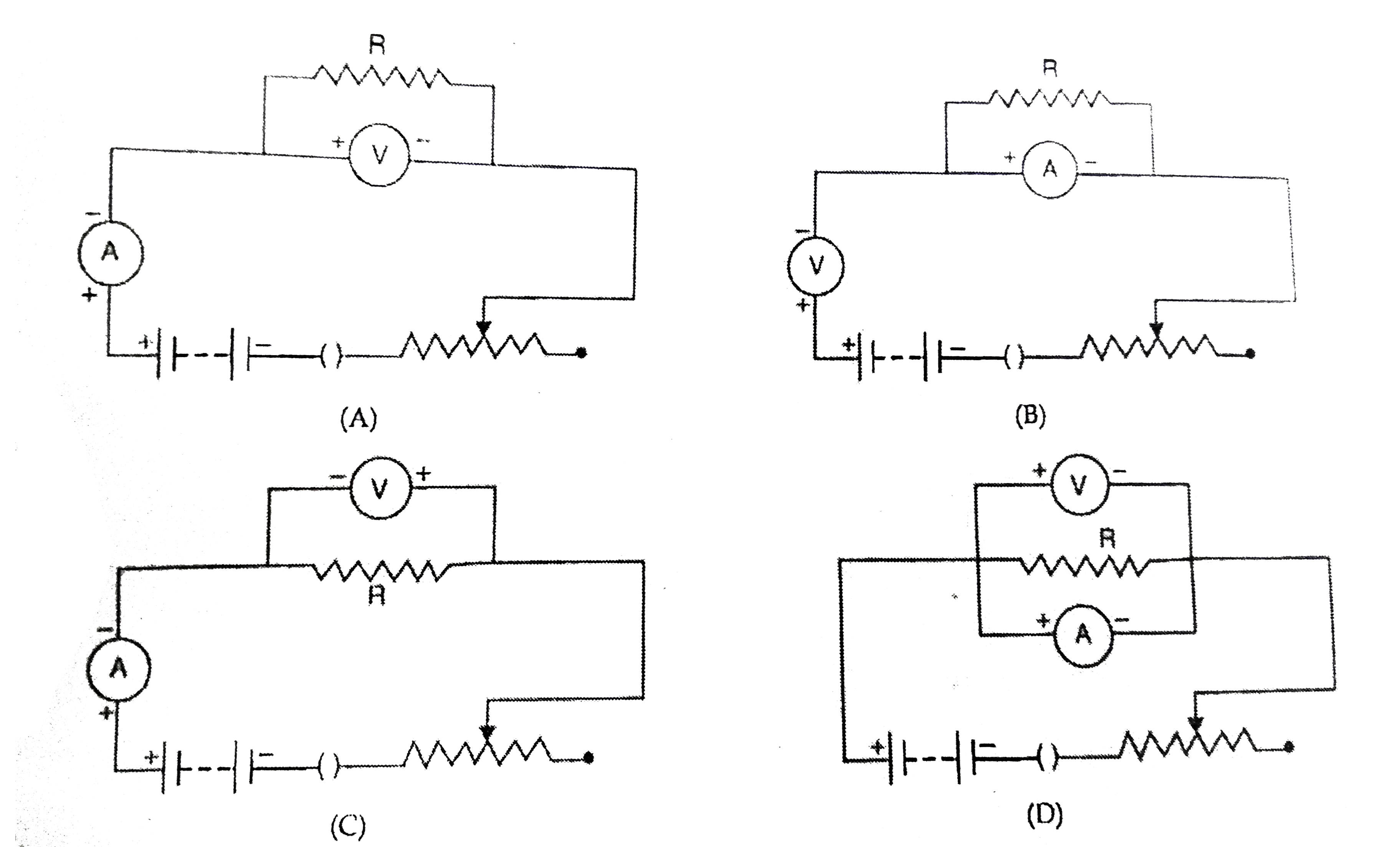
- Consider the following circuits diagrams drawn by four students : ...
Text Solution
|
- The scale of an ammeter is shown below : The least count of this ...
Text Solution
|
- The figure below shows the scale of a voltmeter : The least count o...
Text Solution
|
- A student used the set up given here to study the dependence of curren...
Text Solution
|
- You are given tha following four voltmeters to study the dependence of...
Text Solution
|
- A student arranged an electric circuit as shown alongside : He would...
Text Solution
|
- Four students recorded the readings of the current by observing the po...
Text Solution
|
- The least count of the ammeter shown below is :
Text Solution
|
- Four students measured the reading by observing the position of pointe...
Text Solution
|
- Four students recorded the readings of the potential differece by obse...
Text Solution
|
- In an experiment to find the equivalent resistance of two resistors co...
Text Solution
|
- A student stes up an electric circuit shown here for finding the equiv...
Text Solution
|
- A student while performing the experiment to find the resultant resist...
Text Solution
|
- While performing an experiment to determine the equivalent resistance ...
Text Solution
|
- Choose the appropriate set of apparatus for performing the experiment ...
Text Solution
|
- In the experiment on finding the equivalent resistance of two resistor...
Text Solution
|
- In the experiment on finding the equivalent resistance of two resistor...
Text Solution
|
- The only correct statement for the following electric circuit is :
Text Solution
|