Home
Class 10
PHYSICS
The values of resistance marked on the c...

The values of resistance marked on the coils `R_(1)` and `R_(2)` are found to be correct. A student connects the given resistors in the following manner (as shown in Figure 1).

He then connects the terminals marked X and Y of the above combination of resistors `R_(1)` and `R_(2)` to the terminals marked X and Y in the circuit (shown in Figure 2).
The average value of the ratio V/I in the obervations recorded in the circuit would be :

A

`9 Omega`

B

`6 Omega`

C

`3 Omega`

D

`2 Omega`

Text Solution

Verified by Experts

The correct Answer is:
A

NA
Promotional Banner

Topper's Solved these Questions

  • THE HUMAN EYE AND THE COLOURFUL WORLD

    LAKHMIR SINGH & MANJIT KAUR|Exercise Long Answer Type Question|3 Videos
  • THE HUMAN EYE AND THE COLOURFUL WORLD

    LAKHMIR SINGH & MANJIT KAUR|Exercise NCERT Book|14 Videos
  • THE HUMAN EYE AND THE COLOURFUL WORLD

    LAKHMIR SINGH & MANJIT KAUR|Exercise Long Answer Type Questions|2 Videos
  • TEST PAPER 4

    LAKHMIR SINGH & MANJIT KAUR|Exercise SECTION A|10 Videos

Similar Questions

Explore conceptually related problems

Three students (A), (B) and (C) connect their two given resistors R_(1) and R_(2) in the manners shown below : They connect the terminals marked X and Y above to the terminals marked X and Y in the circuit given below: The record the Ammeter readings (I) for different positions of the rheostat and the corresponding Voltmeter readings (V). The average value of the ratio V/I in their observations would be minimum for :

A student carries out the experiment for studying the dependence of current (I) flowing through a resistor system of R_(1) and R_(2) on the potential difference (V) applied to it by connecting the resistor system to points X and Y of the measuring circuit as shown : The average value of the ratio V/I, of his observations, would then be equal

Three resistors, an ideal cell are connected as shown in figure. The switch is initially open. When we close the swithc, the current in the resistor R_(2) will.

Students A and B connect the two resistors R_(1) and R_(2) given to them in the manners shown below : and then insert them at X and Y into the measuring circuit shown below : We can then say that

Two students (A) and (B) connect their two given resistors R_(1) and R_(2) in the menners shown below : Student (A) connects the terminals marked ( b_(1) ) and (C_(1)) while student (B) connects the terminals marked (d_(2)) and (c_(2)) in their respective circuits at the points marked X and Y. Which one of the following is correct in relation to above arrangements ?

Twelve resistors each of resistance 1 Omega are connected in the circuit shown in figure. Net resistance between point A and H would be

If resistors of resistance R_(1) and R_(2) are connected in parallel,then resultant resistance is "

LAKHMIR SINGH & MANJIT KAUR-THE HUMAN EYE AND THE COLOURFUL WORLD -Multiple Choice Questions
  1. You are given four ammeters A, B, C and D having the least counts men...

    Text Solution

    |

  2. Consider the two circuits A and B given alongside : In the circuits ...

    Text Solution

    |

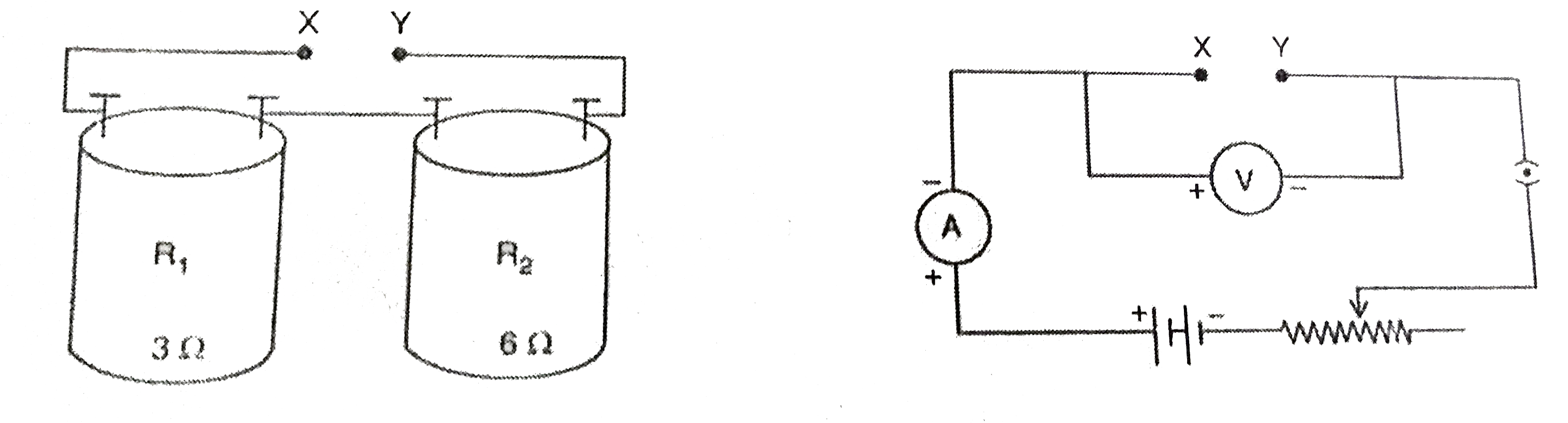
  3. The values of resistance marked on the coils R(1) and R(2) are found t...

    Text Solution

    |

  4. A student using the same two resistors, ammeter, voltmeter and battery...

    Text Solution

    |

  5. Two students made two circuits A and B to determine the resultant resi...

    Text Solution

    |

  6. Four student have made the following circuit diagrams for determining ...

    Text Solution

    |

  7. Consider the following four circuits P, Q, R and S which have been set...

    Text Solution

    |

  8. In order to determine the equivalent resistance of two resistors R(1)...

    Text Solution

    |

  9. To find the resultant resistance of two resistors when connected in se...

    Text Solution

    |

  10. The following apparatus is available in a laboratory : Battery : adj...

    Text Solution

    |

  11. The following pieces of apparatus are available in a laboratory : Ba...

    Text Solution

    |

  12. The ammeter, voltmeter and, resistors R(1) and R(2) connected in the c...

    Text Solution

    |

  13. A student determines the focal length of a device X, by focusing the i...

    Text Solution

    |

  14. The focal length of the concave mirror in the experimental set up, sho...

    Text Solution

    |

  15. While determining the focal length of a concave mirror, a student obta...

    Text Solution

    |

  16. A student obtains a blurred image of a distant object on a screen usin...

    Text Solution

    |

  17. Four students A, B, C and D performed the experiment to determine the ...

    Text Solution

    |

  18. A student has to do the experiment on finding the focal length of a gi...

    Text Solution

    |

  19. Four student A,B,C and D performed an experiment to detemine the focal...

    Text Solution

    |

  20. The parallel rays form the top of a distant tree are incident on a con...

    Text Solution

    |