


Similar Questions
Explore conceptually related problems
Recommended Questions
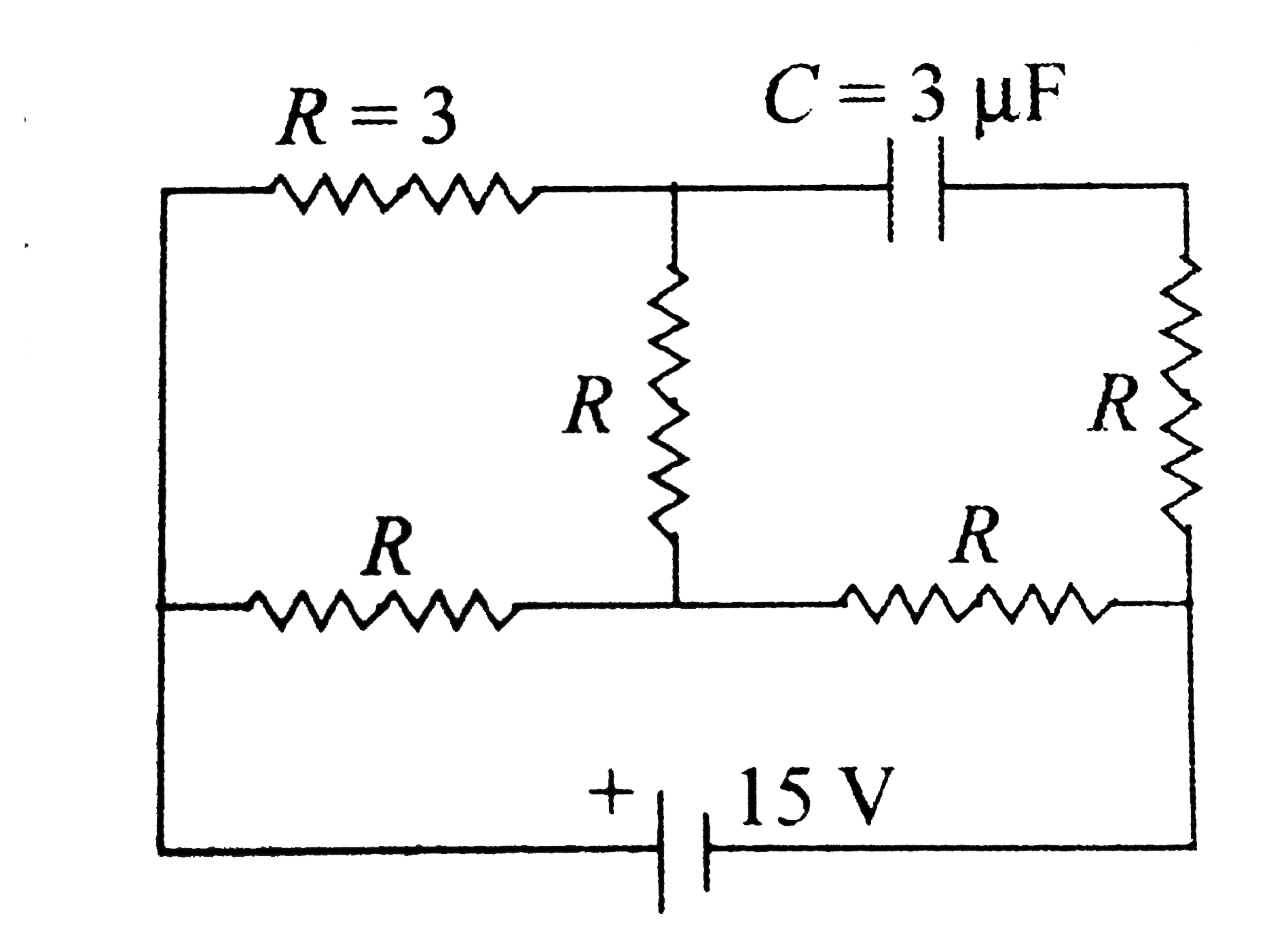
- In the circuit shown in fig. the cell is ideal with emf 15V. Each resi...
Text Solution
|
- In the circuit the potential difference across the capacitor is 10 V ....
Text Solution
|
- In the circuit shown in fig. the cell is ideal with emf 15V. Each resi...
Text Solution
|
- In the given circuit , the potential difference across the capacitor i...
Text Solution
|
- In the shown circuit, all three capacitor are identical and have capac...
Text Solution
|
- In the circuit shown, the cell is ideal , with emf= 15 V. Ecah resista...
Text Solution
|
- In the circuit shown the cell is idea with end =15V each resistance is...
Text Solution
|
- In the fig. shown the circuit is in steady state. what is the potentia...
Text Solution
|
- In the circuit shown here, cells A and B have emf 10 V each and the in...
Text Solution
|