A
B
C
D
Text Solution
Verified by Experts
The correct Answer is:


Topper's Solved these Questions
SEMICONDUCTOR ELECTRONICS : MATERIALS , DEVICES AND SIMPLE CIRCUITS
NCERT FINGERTIPS|Exercise NCERT Exemplar|8 VideosSEMICONDUCTOR ELECTRONICS : MATERIALS , DEVICES AND SIMPLE CIRCUITS
NCERT FINGERTIPS|Exercise Assertion And Reason|15 VideosSEMICONDUCTOR ELECTRONICS : MATERIALS , DEVICES AND SIMPLE CIRCUITS
NCERT FINGERTIPS|Exercise Digital Electronics And Logic Gates|16 VideosRAY OPTICS AND OPTICAL INSTRUMENTS
NCERT FINGERTIPS|Exercise Assertion And Reason|15 VideosWAVE OPTICS
NCERT FINGERTIPS|Exercise Assertion And Reason|15 Videos
Similar Questions
Explore conceptually related problems
NCERT FINGERTIPS-SEMICONDUCTOR ELECTRONICS : MATERIALS , DEVICES AND SIMPLE CIRCUITS -Higher Order Thinking Skills
- If each diode in figure has a forward has a forward bias resistance of...
Text Solution
|
- In the circuit shown in figure, when the input voltage of the base res...
Text Solution
|
- A potential barrier of 0.50 V exists across a P-N junction. If the de...
Text Solution
|
- If an electron approaches the p-n junction from the n-side with a spee...
Text Solution
|
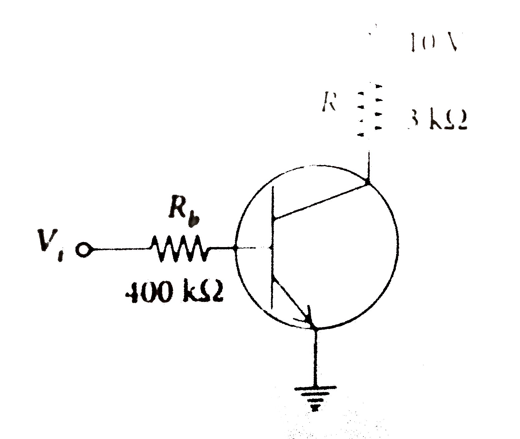
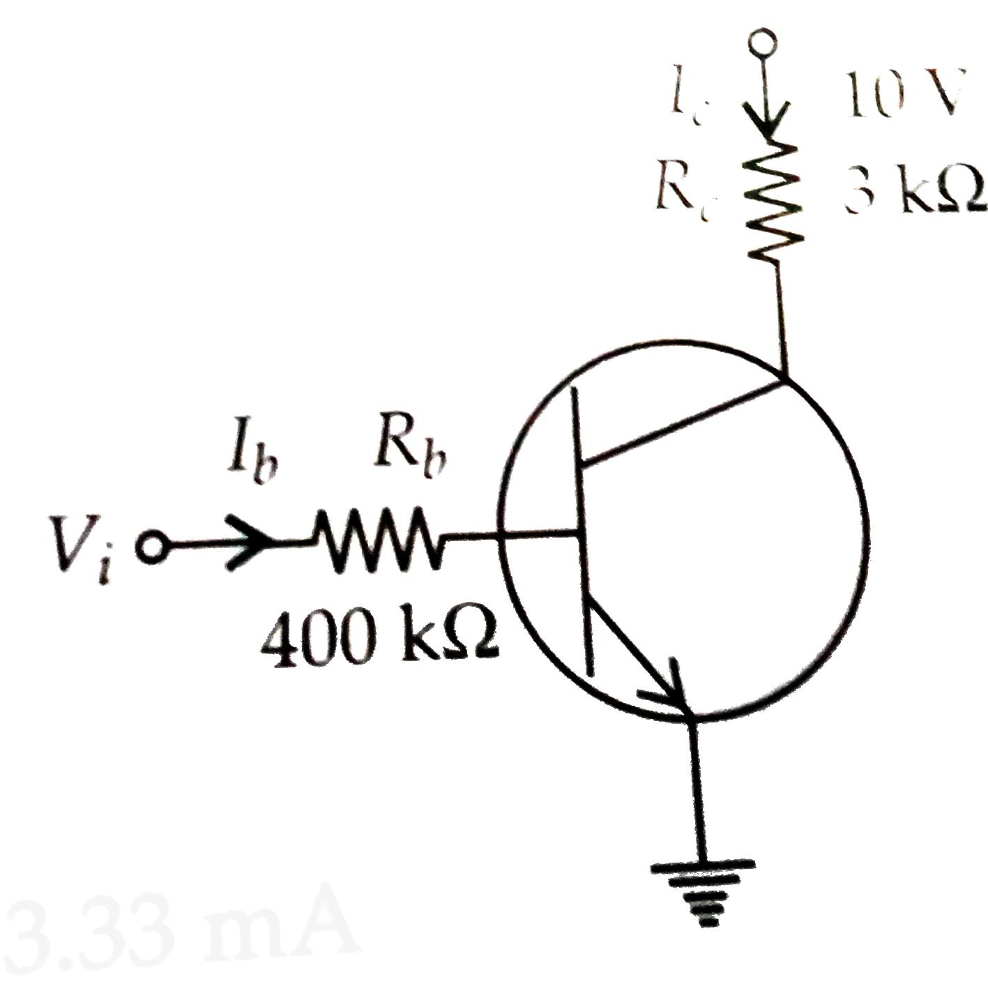
- An n-p-n transistor in a common-emitter mode is used as a simple volta...
Text Solution
|
- The equivalent resistance of the circuit, across AB is given by
Text Solution
|
- In the circuit shown in figure, the silicon and germanium diodes start...
Text Solution
|
- The Boolean expression of the output y in terms of the input A and B f...
Text Solution
|