


Similar Questions
Explore conceptually related problems
Recommended Questions
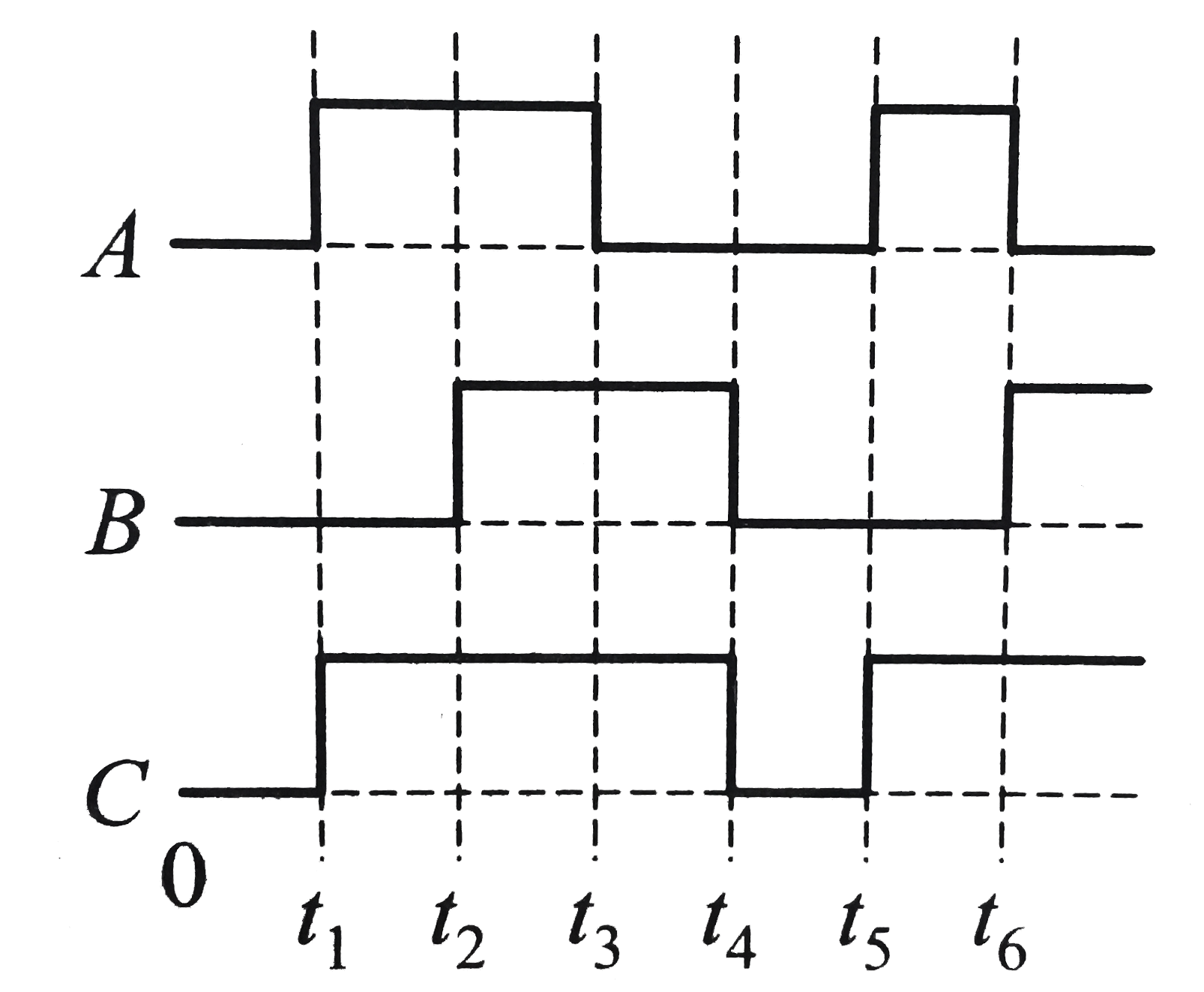
- The figure shows a logic circuit with two inputs A and B and the outpu...
Text Solution
|
- The figure shows a logic circuit with two inputs A and B and the outpu...
Text Solution
|
- Fig, shows a logic gate circuit with two input A and B and the output ...
Text Solution
|
- The following figure shows a logic gate circuit with two inputs A and ...
Text Solution
|
- The following figure shows a logic gate circuit with two inputs...
Text Solution
|
- चित्र में एक लॉजिक परिपथ में दो निवेशी A तथा B और एक निर्गत C दर्शाया ...
Text Solution
|
- निम्नलिखित चित्र में एक तर्क द्वार परिपथ को दिखाया गया है जिसमें दो नि...
Text Solution
|
- The following shows a logic gate circuit with two inputs A and B and t...
Text Solution
|
- निम्नलिखित चित्र में एक AND तर्क द्वार परिपथ को दिखाया गया है जिसमें द...
Text Solution
|