


Similar Questions
Explore conceptually related problems
Recommended Questions
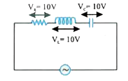
- In series L-C-R circuit as shown in figure the voltage of the source i...
Text Solution
|
- Assertion: In series L-R circuit voltage leads the current. Reason: In...
Text Solution
|
- In the circuit shown in figure the voltage in L and in C are .
Text Solution
|
- In series LCR circuit, the voltages across R, L and C are shown in the...
Text Solution
|
- In a series L.C.R. circuit, the potential drop across L , C and R resp...
Text Solution
|
- In a circuit L,C and R are connected in series with an alternating vol...
Text Solution
|
- In a circuit L, C and R are connected in series with an alternating vo...
Text Solution
|
- In series L-C-R circuit as shown in figure the voltage of the source i...
Text Solution
|
- In series L-C-R circuit as shown in figure the voltage of the source i...
Text Solution
|