A
B
C
D
Text Solution
Verified by Experts
The correct Answer is:


Topper's Solved these Questions
SEMICONDUCTOR ELECTRONICS
NARAYNA|Exercise EXERCISE -2 (H.W) (LOGIC GATE)|6 VideosSEMICONDUCTOR ELECTRONICS
NARAYNA|Exercise EXERCISE -3|43 VideosSEMICONDUCTOR ELECTRONICS
NARAYNA|Exercise EXERCISE -2 (H.W) (APPLICATIONS OF JUNCTION DIODE AS RECTIFIER)|4 VideosSEMI CONDUCTOR DEVICES
NARAYNA|Exercise Level-II (H.W)|36 VideosWAVE OPTICS
NARAYNA|Exercise Exercise - 4 Polarisation|9 Videos
Similar Questions
Explore conceptually related problems
NARAYNA-SEMICONDUCTOR ELECTRONICS-EXERCISE -2 (H.W) (TRANSISTORS)
- For a CE-transistor amplifier, the audio signal voltage across the col...
Text Solution
|
- In a common emitter amplifier the load resistance of the output circui...
Text Solution
|
- For a transistor connected in common emitter mode, the voltage drop ac...
Text Solution
|
- In an n-p-n transistor 10^(10) electrons enter the emitter in 10^(-6)s...
Text Solution
|
- In the cuircuit shown here the transistor used has a current gain beta...
Text Solution
|
- An N-P-N transistor is connected in common-emitter configuration in wh...
Text Solution
|
- For a CE transistor amplifier, the audio signal voltage across the col...
Text Solution
|
- In a silicon transistor, the base current is changed by 20 muA. This r...
Text Solution
|
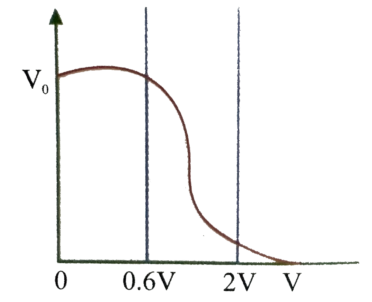
- Figure shows the transfer characteristics of a base biased CE transist...
Text Solution
|